Concrete Pump Parts Knowledge
Concrete Pump Pipe Diameter: Aggregate, Pressure, and Blockage Trade-Offs
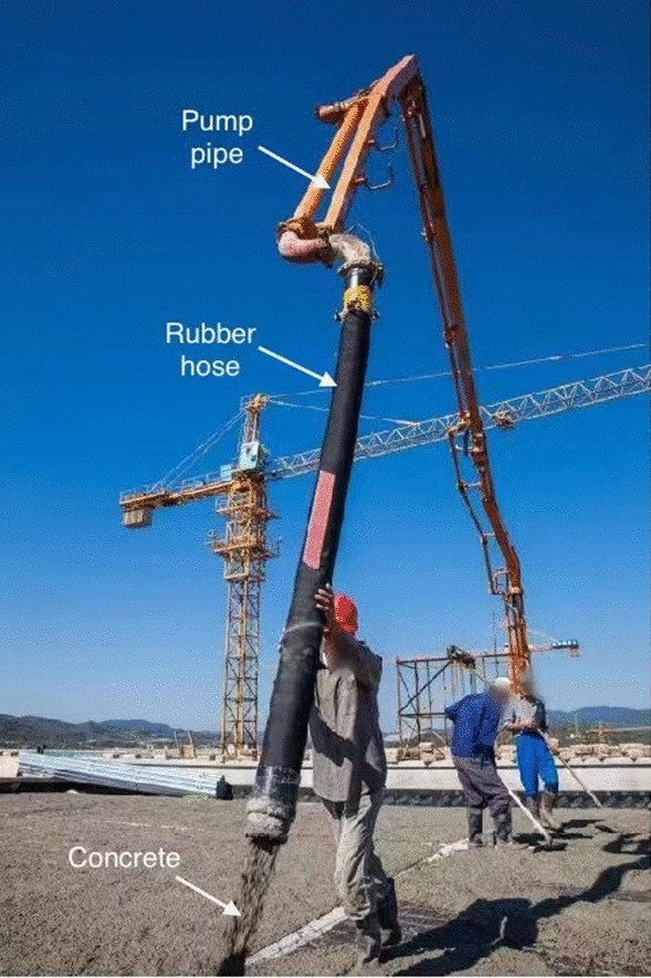
A concrete pump pipe diameter should not be selected from the pump’s advertised output or a familiar nominal line size alone. The controlling dimension is the smallest actual concrete passage in the complete route, considered together with the largest aggregate particles, aggregate shape and grading, target placing rate, line length, elevation, bends, reducers, and flexible hose. A line that is too small can create a local restriction and high resistance. A larger line can reduce velocity at the same output, but it also holds more concrete, adds filled weight, and does not rescue an unstable mix.
The practical question is therefore not “Which pipe size is standard?” It is “Which complete pump-and-line combination can pass this approved concrete mix at the required rate without exceeding equipment, component, or site limits?”
What pipe diameter changes in a concrete pumping system
Pipe diameter affects several linked conditions. First, it sets the clearance available for coarse aggregate, fibers, and any agglomerated material. Second, for a given volumetric output, it determines average concrete velocity: reducing the internal flow area requires the material to move faster. Third, it changes the relationship among the concrete core, the mortar-rich layer at the wall, and the pressure required to maintain flow.
Fresh concrete is not water, so a simple liquid-pipe friction calculation is not an adequate selection method. ACI 304.2R describes pumped concrete as moving with a thin mortar or grout layer at the pipeline wall. Pumping research likewise shows that pressure loss depends on the properties of this lubrication layer, the rheology of the bulk concrete, flow rate, and pipe radius. Diameter matters, but it cannot be separated from the concrete being pumped.
Diameter also changes the operational burden. A larger line contains more concrete per metre, becomes heavier when full, and requires more material during priming and cleaning. A smaller hose may be easier to position at the discharge, yet it can become the highest-resistance and smallest-clearance part of the route. Selection is a system trade-off rather than a rule that the largest or smallest available line is always best.
Nominal line size is not the same as the controlling bore
Market listings commonly describe concrete pump pipe as DN100, DN125, 4-inch, 5-inch, or similar shorthand. These names are useful for identifying a product family, but they should not replace confirmation of the actual internal passage. Wall construction, wear condition, hose reinforcement, end fittings, and manufacturer-specific geometry can affect the usable bore.
Map the complete path from the hopper transfer area to the discharge point. The smallest passage may be:
- the valve or pump outlet rather than the straight pipe;
- the throat of a reducer;
- an elbow with hardened buildup or wear-related deformation;
- a flexible hose whose bore is smaller than the upstream steel line;
- a kinked, crushed, internally damaged, or incorrectly connected hose;
- a gasket or end connection intruding into the flow path.
A 5-inch-class main line followed by a smaller terminal hose is not a 5-inch system for aggregate-clearance purposes. The terminal restriction, or any smaller point upstream, controls what must pass. The same logic applies when several nominal sizes are connected through reducers.
Use the aggregate-to-diameter rule as a screening check, not a guarantee
A recurring industry rule is that the line’s internal diameter should be roughly three to four times the largest aggregate size. A REED B50 technical manual expresses the relationship this way. The U.S. Bureau of Reclamation’s review of pumping cement-based materials gives a more qualified form: it cites an ACI limit of one-third of the smallest pump or pipeline inside diameter for crushed coarse aggregate and notes that well-rounded aggregate may be allowed up to 40 percent of the pipe inside diameter.
Those statements are useful, but they do not mean that dividing a nominal pipe label by three proves pumpability. The check can fail for several reasons:
| Condition to confirm | Why the simple ratio is insufficient |
|---|---|
| Actual maximum particle | “Nominal maximum aggregate size” is a grading designation. An oversize particle, contamination, or agglomeration can be larger than the value used in a quick calculation. |
| Aggregate shape | Angular or elongated particles do not rearrange through a restriction as readily as well-rounded particles. |
| Combined grading | A pumpable mix needs enough mortar and suitable fine/coarse distribution to keep the coarse fraction suspended and maintain the wall layer. |
| Mixture stability | Segregation can allow paste to move ahead while a coarse, dry concentration forms a plug. |
| Fibers and additions | Fibers can interact with coarse particles and local restrictions; a particle-size check alone does not represent that behaviour. |
| Smallest passage | The pipe may satisfy the ratio while a reducer, valve opening, hose, or damaged fitting does not. |
The ratio is best used as an early rejection test. If the approved mix clearly exceeds the pump or line manufacturer’s aggregate limit, do not attempt to compensate by adding water, increasing pressure, or relying on the valve to break particles. If it passes the ratio, continue the engineering review; it has not yet passed the job.
Why a smaller line raises more than blockage risk
At the same delivery rate, a smaller internal area means higher average velocity. The required pressure response is mix- and route-specific, but full-scale and analytical pumping studies consistently treat flow rate and pipe radius as important pressure-loss variables. Hoses, bends, and reductions add further resistance. The REED manual also warns that concrete flows with less back pressure through rigid pipe than through hose and recommends minimizing hose bends.
This creates an important diagnostic distinction. A pump that reaches high hydraulic load after a smaller hose or reducer is installed may be responding to the new delivery resistance; it does not automatically have a defective valve or delivery cylinder. Conversely, fitting a larger pipe will not correct poor cylinder filling, piston bypass, valve leakage, or an unstable concrete mix. Record what changed before ordering parts.
Do not use a pressure spike as a field experiment. A blockage can retain dangerous energy even after pumping stops. Follow the pump manufacturer’s shutdown and pressure-relief procedure, keep personnel clear of the delivery system, and never open a clamp until the line has been confirmed depressurized by the approved method.
The pump, valve, reducer, and line must be treated as one flow path
Twin-cylinder concrete pumps first draw material into the pumping chambers and then direct alternate delivery strokes through a transfer valve. The bore and condition of the Concrete Pump Delivery Cylinders influence filling and piston sealing, but their nominal diameter does not independently define the downstream line that should be used.
The selected Concrete Pump S-Valve Assembly or Concrete Pump Rock Valve, outlet housing, reducer, pipeline, elbows, couplings, and discharge hose form one concrete passage. If one element has a smaller opening, hardened buildup, poor alignment, or paste leakage, it can dominate system behaviour. That is why a pipe-size decision made without the pump model, installed valve arrangement, and outlet configuration is incomplete.
Pressure ratings also belong to the system review. Pipe, hose, elbows, couplings, gaskets, and end fittings must be suitable for the anticipated working condition and for the pump’s possible concrete pressure. Similar-looking ends do not prove equal pressure capability. Worn delivery components require inspection under the owner’s program; diameter compatibility does not make a worn or unrated component safe.
A practical concrete pump pipe diameter selection sequence
- Obtain the approved mix information. Record the concrete designation, nominal maximum aggregate size, any available absolute top-size control, aggregate shape and grading, fiber type and dosage where applicable, consistency specification, and relevant producer guidance. Do not redesign the mix at the pump.
- Map the smallest internal passage. Check the pump outlet, valve path, reducers, steel pipe, bends, hoses, couplings, and terminal equipment. Use actual manufacturer data or measurements made on safely isolated, clean components.
- Screen aggregate clearance. Apply the applicable OEM limit first. Use the one-third or three-to-four-times relationship only as a secondary engineering check, with the more conservative treatment for angular aggregate and uncertain grading.
- Define the duty. Record required output, total length, vertical rise and fall, number and radius of bends, reducer locations, hose lengths, planned interruptions, and placement method. The same mix and diameter can behave differently on two routes.
- Check pressure and power capability. Use the pump manufacturer’s performance data and a project-specific pressure calculation or approved sizing method. Maximum theoretical output and maximum pressure should not be assumed to be available simultaneously.
- Verify every delivery component. Confirm pressure rating, wall or wear condition, end style, coupling and gasket compatibility, support and anchorage requirements, and hose condition. The weakest component governs the allowable system pressure.
- Plan priming, operation, and cleaning. Line volume, diameter, and route affect primer demand, retained concrete, cleanup method, and handling. Follow the product, pump, and project procedures rather than a fixed universal quantity.
- Record a controlled baseline. On an approved setup, note output setting, stroke behaviour, concrete pressure or approved gauge readings, mix ticket, and any unusual movement. This gives maintenance teams evidence if performance later changes.
How to read common symptoms after a line-size change
| Observation | Possible mechanism | What to verify before concluding |
|---|---|---|
| Pressure increases after adding a smaller hose | Higher local velocity, hose resistance, a kink, or reduced effective bore | Hose ID and rating, routing, internal damage, mix, output, and comparison with the previous setup |
| Blockage repeatedly develops at one transition | Abrupt reduction, oversize aggregate, buildup, leakage, or damaged fitting | Depressurized inspection, actual throat size, gasket position, cleanliness, and batch grading information |
| Output falls while stroke rate appears normal | Line resistance, incomplete cylinder filling, piston bypass, or valve leakage | Compare both cylinder sides, hopper feed, water-box evidence, valve sealing, line layout, and measured output |
| Concrete moves well in steel pipe but poorly through long hose | Additional flexible-hose resistance or local deformation | Required hose length, bends, support, bore, internal wear, and OEM layout guidance |
| Changing to larger pipe does not stabilize flow | Mix instability, insufficient wall-layer formation, filling fault, or transfer-valve problem | Mix records, priming, supply continuity, cylinder filling, sealing, switching, and remaining restrictions |
These observations indicate where to investigate; none proves a single root cause. The safest diagnosis separates concrete quality, route resistance, and pump condition instead of attributing every high-pressure event to pipe diameter.
Information to provide when specifying or purchasing a delivery-line system
A useful inquiry should identify the pump make, model, serial range where relevant, valve and outlet arrangement, existing line nominal size, verified internal passage, pipe and hose lengths, reducer endpoints, end style, coupling type, required pressure rating, and the planned route. Include the approved concrete’s aggregate and fiber information, target output, vertical rise, bends, and terminal hose requirement.
For replacement sections, also document the markings on the original component, outside dimensions needed for fit, wall or wear-class information, and clear photographs of both ends. Do not ask a supplier to match a line only from “DN125” or “5-inch”; those labels omit the pressure class, end geometry, wear condition, and system interfaces that determine whether the part is suitable.
Conclusion
Concrete pump pipe diameter selection starts with the smallest real flow passage and the approved concrete mix, then expands to output, route resistance, component ratings, handling, priming, and cleaning. The familiar aggregate-to-diameter ratio is valuable for screening, especially when aggregate shape is considered, but it is not a pumpability certificate.
A defensible selection records the mix, maps every restriction from delivery cylinder to end hose, checks the pump manufacturer’s limits, and verifies the pressure capability and condition of the entire delivery system. That approach prevents a nominal pipe label from hiding the actual bottleneck.
Technical references
- ACI 304.2R-17 preview: Guide to Placing Concrete by Pumping Methods
- U.S. Bureau of Reclamation: Pumping Cement-Based Materials
- REED B50 Trailer Concrete Pump Technical Manual
- Choi, Kim, and Kim: Prediction of Concrete Pumping Using Various Rheological Models
- The Concrete Society: Concrete for pumping