Concrete Pump Parts Knowledge
Concrete Pump Rock Valve Tension Nut: Adjustment Limits and Kidney-Seal Wear
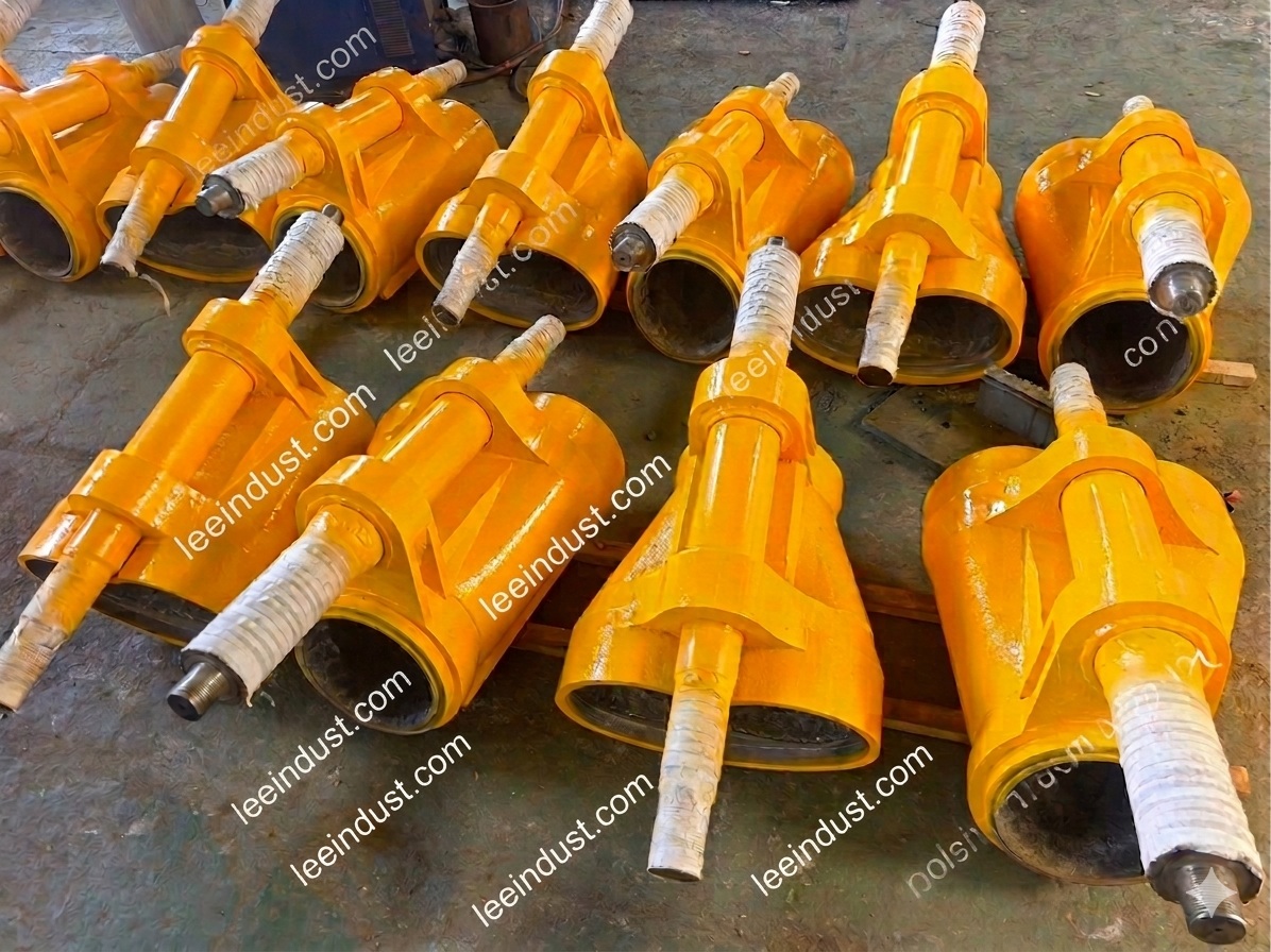
A concrete pump Rock Valve tension nut should be adjusted only to control free play at the kidney-seal end of the valve. It is not a general-purpose way to force the cutting ring harder against the inlet wear surface. On Schwing SP Rock Valve models, the manufacturer specifically separates these functions: the tension nut positions the kidney-seal end, while a pressure spring compensates contact at the cutting-ring end. Confusing the two can leave the original leakage unresolved while accelerating kidney-seal wear or making the valve harder to shift.
This distinction is easy to miss because both sealing interfaces are carried by the same moving valve body. A technician sees concrete bypass, a loose-feeling valve, or a new seal that fails early and may be tempted to tighten the most visible adjuster. The correct decision begins by identifying which end has lost control, checking the mating parts, and using the serial-number-specific service procedure.
What Does the Rock Valve Tension Nut Actually Adjust?
The tension nut controls axial position or free play at the Rock Valve’s outlet, commonly called the kidney-seal end. The kidney seal runs against a kidney-shaped housing lining or outlet wear surface. The nut, setting disc or spacer, keeper bolt, shaft, end cover, seal, and liner work as one positional system.
The opposite end has a different sealing job. At the inlet side, the cutting ring runs against a wearing insert, spectacle plate, or related inlet surface around the material-cylinder openings. In the Schwing SP arrangement described in the operation manual, a pressure spring—not the tension nut—compensates wear at this cutting-ring interface.
| Interface or component | Primary job | What controls contact in the cited SP design | Common diagnostic mistake |
|---|---|---|---|
| Kidney seal and housing lining | Seal and guide the outlet-side interface | Tension-nut position and associated setting/retaining parts | Tightening until all visible movement disappears, without inspecting the seal and liner |
| Cutting ring and inlet wear surface | Seal the active delivery cylinder to the Rock Valve inlet | Pressure spring and condition of the ring and mating wear surface | Using the tension nut to correct concrete backflow at the cylinder mouths |
| Valve shaft, bushings, cover, and supports | Maintain controlled movement and alignment | Model-specific fits, fasteners, bearings, and axial settings | Assuming every perceived movement is tension-nut free play |
| Hydraulic shift system | Move the valve briskly between end positions | Shift cylinder, hydraulic supply, controls, and accumulator where fitted | Blaming mechanical adjustment for a slow or incomplete hydraulic shift |
Schwing’s own ROCK Valve technical material lists the kidney seal, cutting ring, wearing insert, housing lining, and delivery pistons as separate wear items. That parts map is useful diagnostic evidence: one adjuster cannot restore every worn interface in the concrete path.
Why Can Over-Tightening Damage the Kidney Seal?
Over-tightening increases compression and sliding load at the kidney-seal interface; it does not renew a worn seal or flatten a grooved liner. The SP 500/750/1000/1250 manual tells the technician to turn the tension nut by hand to the furthest reachable keeper-bolt hole and to return to the previous hole if the next one cannot be reached by hand. It explicitly warns against using a wrench to force the nut into the next position because over-tightening causes premature kidney-seal wear.
The mechanical reason is straightforward. The kidney seal must remain in controlled contact while the Rock Valve switches repeatedly. Excessive axial load raises friction and can squeeze or distort the elastomeric element. The hydraulic circuit then has to move the valve against a larger mechanical resistance. A valve that shifts reluctantly after adjustment is not “sealed better”; it may be over-preloaded, contaminated, misassembled, or suffering from another mechanical fault.
Too much grease can also mislead the adjustment. Schwing service-training material warns that grease accumulated in the pressure-spring chamber can behave like a spacer and increase spring preload. Grease belongs at the specified lubrication points and in the specified amount. Packing a chamber with grease is not a substitute for correct component position.
Does Concrete Backflow Mean the Tension Nut Is Loose?
Not necessarily. Concrete or paste returning toward the hopper often points technicians toward the inlet sealing system: the cutting ring, wearing insert or spectacle plate, pressure spring, valve end position, or adjacent cylinder mouth. Tension-nut adjustment acts at the kidney-seal end in the cited Rock Valve design, so it should not be the automatic response to inlet-side backflow.
Before drawing a conclusion, locate the leakage path. Evidence around the outlet-side kidney seal is different from material pulsing through a cylinder opening in the hopper. A washed-clean pump inspected under the manufacturer’s safe procedure may reveal polished tracks, grooves, a damaged seal lip, embedded aggregate, loose retaining hardware, or uneven contact. Each observation points to a different verification step.
| Observation | Possible mechanism | What to verify before adjusting |
|---|---|---|
| Free play at the kidney-seal end | Tension-nut position, setting-disc position, worn seal, worn housing lining, shaft/support wear | Exact model procedure, keeper hardware, seal profile, liner condition, and measured play |
| New kidney seal wears rapidly | Excessive preload, dry switching, aggressive cleaning chemical, grooved mating surface, dirt behind the seal, incorrect part | Adjustment history, lubrication/wetting practice, liner track, seal orientation, and part number |
| Valve shifts slowly after adjustment | Excessive mechanical load, debris, shaft/bushing problem, hydraulic fault, or incomplete end travel | Whether the symptom began with adjustment; safe manual/mechanical checks; hydraulic diagnosis separately |
| Concrete moves back at a material-cylinder opening | Cutting ring or inlet wear surface wear, weak/damaged pressure spring, incomplete valve travel | Inlet-side wear pattern and spring system; do not assume the kidney-end nut is the remedy |
| Free play returns quickly | Wear rather than simple loss of setting, damaged keeper system, settling after incorrect assembly | Seal, liner, shaft, bushings, end cover, setting disc, nut threads, and retaining bolt |
A Safe Inspection Sequence Before Any Adjustment
Rock Valve maintenance places personnel near the hopper, valve, shaft, and stored-energy hydraulic circuit. Turning off a control does not prove that the valve cannot move. The American Concrete Pumping Association warns that a transfer valve can still move after shutdown because accumulator pressure may remain. The machine must be isolated, the applicable hydraulic pressure released and verified at zero, and the OEM lockout procedure followed before guards or hopper access points are opened.
- Identify the machine and valve version. Record pump model, serial number, pump-kit designation, Rock Valve size, and the manual revision. Similar-looking nuts and discs do not establish an interchangeable procedure.
- Separate inlet-side and outlet-side symptoms. Record where concrete or water appears, where free play is observed, whether the problem occurs in both valve positions, and whether the shift remains brisk.
- Clean before measuring. Hardened paste, trapped aggregate, and packed grease can hold components away from their intended positions. Cleaning must use an OEM-approved method that does not expose personnel to stored pressure or unexpected movement.
- Inspect the whole load path. Check the kidney seal, housing lining, shaft, bushings, end cover, setting disc or spacer, tension nut, keeper bolt, cutting ring, pressure spring, and inlet wear surface. A new seal against a deeply grooved liner is not a complete repair.
- Apply only the model-specific criterion. Some SP manuals use a hand-to-keeper-hole method. Other Rock Valve manuals specify measured axial play or a different setting sequence after parts have seated. Do not combine steps or dimensions from different models.
- Validate movement and leakage under the OEM recommissioning procedure. Refit every guard and interlock, account for tools, and observe from a protected position. If movement worsens, stop and investigate rather than adding more preload.
This is an inspection framework, not a universal adjustment instruction. Powered cycling, hopper access, fastener torque, clearance, and lubrication details must come from the current manual and be performed by trained personnel.
Why Adjustment Numbers Cannot Be Copied Between Rock Valves
Published Schwing documents themselves demonstrate model variation. An older Rock Valve service procedure gives a model-specific new-parts clearance in the kidney-seal area, while a separate truck-mounted-pump manual uses a different clearance range and a seating sequence before final axial-play adjustment. The SP line-pump manual instead emphasizes a hand-tight keeper-hole method for its tension nut.
These are not competing “correct” numbers. They describe different valve versions, wear-part stacks, shaft arrangements, and procedures. Even within one brand, the following can change the acceptable setting:
- Rock Valve size and long/short body design;
- kidney-seal profile and housing-liner thickness;
- new versus reused mating parts;
- setting-disc or spacer geometry and keeper-hole spacing;
- shaft, bushing, bearing, end-cover, and slewing-lever arrangement;
- the procedure used to seat the parts before final verification.
The same caution applies across valve families. A REED S-tube manual describes a castle-nut adjustment intended to control wear-ring contact at the hopper wear plate. That procedure should not be transferred to a Schwing Rock Valve tension nut, whose documented function is at the kidney-seal end. Similar external hardware does not mean the internal load path is the same.
When Should Parts Be Replaced Instead of Tightened?
Adjustment is reasonable only when the applicable manual permits it, the wear parts remain serviceable, and the setting can be achieved without forcing the mechanism. It cannot restore missing elastomer, remove deep grooves, rebuild a worn shaft, correct an oval bushing, repair damaged threads, or flatten a distorted cover.
Replacement or a broader repair assessment is more appropriate when the kidney seal is cracked, swollen, permanently compressed, incorrectly profiled, or worn past its OEM limit; when the housing lining has a wear track beyond the permitted depth; when the setting will not hold; or when correct adjustment makes the valve bind. Repeated seal failure is especially important evidence. It suggests that the mating surface, preload, cleaning chemistry, dry-switching history, part identification, or supporting hardware has not been corrected.
When the complete transfer component is damaged, buyers can review the mapped Concrete Pump Rock Valve page and submit the old-part information for replacement review. A quotation should distinguish the valve body from the kidney seal, housing lining, setting disc, tension nut, keeper hardware, shaft, bushings, cutting ring, pressure spring, and inlet wear parts.
What Information Should a Repair Workshop Record?
A useful service record links the symptom to the actual parts stack. Include the pump brand, exact model, serial number, pump-kit or valve designation, Rock Valve inlet and outlet size, old part numbers, photographs from both ends, measured free play, kidney-seal condition, housing-liner wear track, shaft and bushing observations, tension-nut and keeper condition, and the result of a controlled post-repair shift check. Record which parts were new and which were reused.
For purchasing, avoid an inquiry that says only “kidney seal DN180” or “Rock Valve nut.” Marketplaces list several seal sizes, setting discs, tension nuts, liners, and valve bodies under overlapping terminology. A nominal diameter does not confirm the seal cross-section, shaft arrangement, setting-disc pattern, or compatibility with the existing liner.
Frequently Asked Questions
Should the Rock Valve tension nut be tightened with a wrench?
Not on the SP models covered by the cited Schwing procedure. That manual instructs hand adjustment to the reachable keeper-bolt position and warns that wrench-forcing the next hole can prematurely wear the kidney seal. Use the procedure for the exact machine; a wrench may still be required for disassembly in a separate service operation.
Will a tighter tension nut stop leakage at the cutting ring?
It should not be assumed. In the cited Rock Valve design, the tension nut acts at the kidney-seal end, while cutting-ring contact is controlled by the pressure spring and the condition of the inlet wear parts. Locate the leakage before changing adjustment.
Can the Rock Valve be cycled dry after a kidney-seal repair?
Schwing manuals warn against dry Rock Valve operation because it can damage the kidney seal. Follow the specified wetting or lubrication method and the controlled seating procedure for the machine.
Does correct adjustment prove the kidney seal is reusable?
No. The nut may take up permitted free play, but it cannot reverse cracking, swelling, loss of seal profile, or excessive liner wear. The seal and its mating surface still require independent acceptance checks.
Conclusion
The Rock Valve tension nut is a local adjustment with a specific purpose: controlling the kidney-seal end of the valve. It should not be used as a universal response to concrete backflow, cutting-ring wear, slow switching, or every form of valve movement. A reliable repair separates the two sealing interfaces, removes stored energy, inspects the complete parts stack, applies the exact OEM criterion, and replaces damaged wear parts rather than hiding them with preload.
Technical Sources
- Schwing SP 500 / 750 / 1000 / 1250 Operation Manual — model-specific tension-nut, kidney-seal, cutting-ring, and pressure-spring guidance.
- Schwing Operation Manual for SP Rock Valve Models — weekly free-play check, hand-adjustment limit, and stored-energy safety.
- Schwing S 47 SX III Operating Instructions — Rock Valve seating, axial-play, cross-tightening, and dry-switching precautions.
- Schwing ROCK Valve System: Wear Parts, Maintenance and Inspection — identification of kidney seal, cutting ring, wearing insert, and housing lining as separate wear components.
- REED Rock Master A30 Technical Manual — contrasting S-tube wear-ring adjustment and stored-energy precautions.
- American Concrete Pumping Association: Hopper and Back-End Injury Prevention — hopper guarding and residual accumulator-pressure hazards.