Concrete Pump Parts Knowledge
Concrete Pump Slewing Cylinder Bushings: Lost Motion, Wear Checks, and Ordering Data
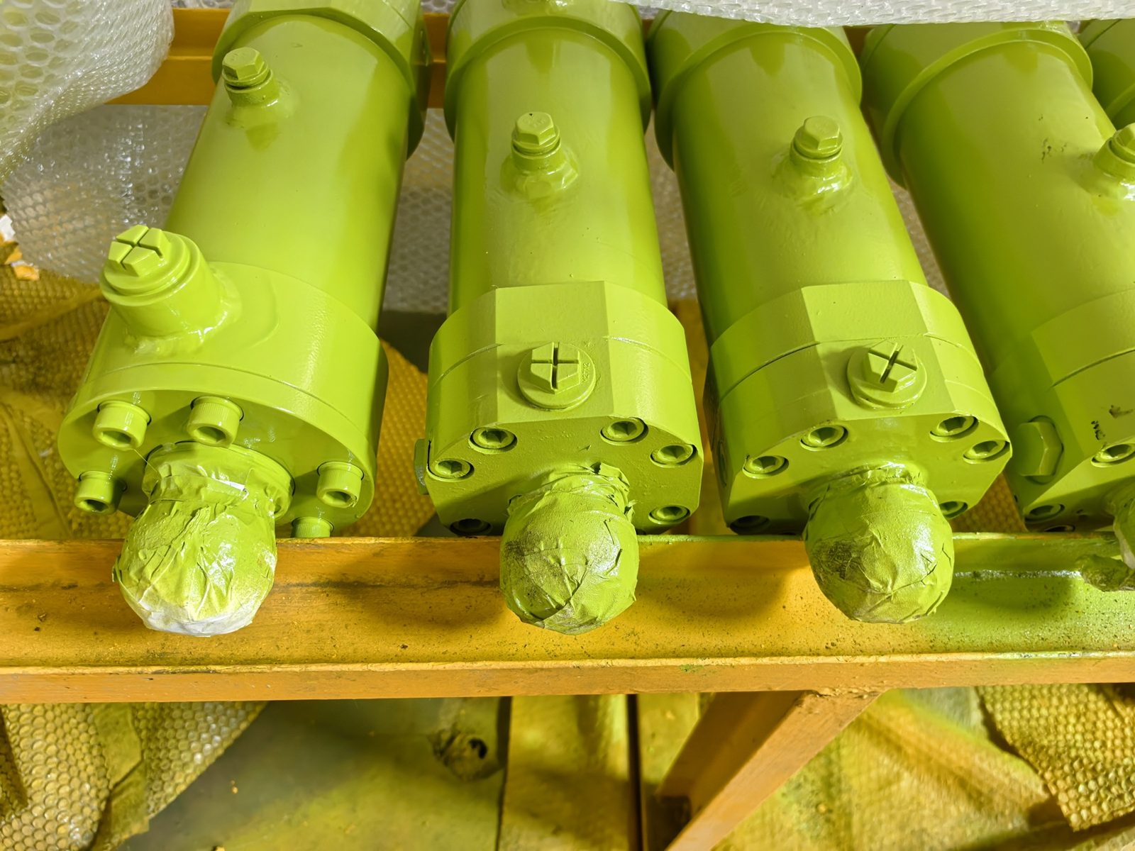
A worn concrete pump slewing cylinder bushing can create lost motion even when the hydraulic cylinder itself is not leaking internally. The rod begins to move, but clearance at a pin, clevis, support, or swing axle is taken up before the valve linkage follows. This may produce a knock at reversal, inconsistent end position, or a switching complaint that is wrongly blamed on seals or hydraulic pressure.
Terminology complicates diagnosis. Parts books use bushing, split bushing, support bushing, swing axle bushing, and shift-cylinder bushing for different interfaces. A cylinder seal kit may also contain internal guide rings, while the S-valve shaft has separate bearings or bushes. These parts are not interchangeable. Start by locating the clearance, not by ordering the first part described as a “swing-cylinder bush.”
What does a slewing cylinder bushing do?
An external slewing cylinder bushing provides a replaceable bearing surface where the actuator or connected swing mechanism pivots. It carries local pin load, preserves the intended pivot geometry, and allows articulation without the pin wearing directly into a more expensive cylinder eye, support, or machine structure.
This is different from sealing hydraulic pressure. A worn external bush can produce free movement while the piston and rod seals remain functional. Conversely, a cylinder can bypass internally while its pins and bushes are sound. Both faults may make switching feel slow, but the evidence and repair scope differ.
OEM information confirms that layouts vary. The Multiquip Mayco LS600P parts manual identifies a swing axle bushing grease point and separate clevis and pivot-bracket lubrication points. A REED B30 manual uses its own swing-ram arrangement. Schwing-Stetter’s spare-parts catalog lists a slewing cylinder, split bushing, slewing pivots, and cylinder support as distinct parts. “Slewing cylinder bushing” is therefore a search term, not a complete identification.
Which bushing are you inspecting?
| Component | Location | Evidence when worn | Common confusion |
|---|---|---|---|
| External eye or clevis bushing | Between a cylinder end and its pin | Relative movement, impact marks, oval wear | Internal rod guide |
| Swing axle, pivot, or support bushing | Valve linkage or machine support | Lost motion between cylinder and lever; grease-path problems | Part of every complete cylinder |
| Internal guide or wear ring | Inside the hydraulic cylinder | Guide clearance, uneven contact, seal distress after disassembly | External pin bushing |
| Valve-shaft bearing or bush | Supporting the S-valve or rock-valve shaft | Shaft play, seal or alignment trouble, valve resistance | Cylinder mounting bush |
The distinction changes purchasing responsibility. A cylinder supplier may supply the actuator and a mounted rod eye but not the machine-side pivot, support block, pin, shims, or valve-shaft bearing. A “complete cylinder” quotation does not prove that every worn interface is included.
How does wear create lost motion?
At each reversal, cylinder force changes side at the mounting joint. If radial clearance has increased, the rod or barrel end moves across that clearance before useful linkage rotation begins. The pin may contact one side of the worn bore during one stroke and the opposite side during the return. This can produce a visible jump or audible knock.
Lost motion changes the relationship between actuator travel and valve position. It can delay when the lever starts moving, consume part of the available travel, and add impact when the joint finally contacts. This does not automatically mean the valve fails to seal; the effect depends on design, adjustment, remaining stroke, pressure, and wear location. It does mean that cylinder movement alone no longer proves accurate valve movement.
Wear can also change load direction. A joint that no longer holds its designed center may place off-axis load on the rod eye, gland, rod, or linkage. That makes an external mounting fault relevant to repeated seal leakage or rod damage. A new Concrete Pump Slewing Cylinder should not be installed into unchecked pins and supports.
Does a reversal knock prove bushing wear?
No. A knock is an observation, not a root-cause diagnosis. Pin or bushing clearance is one possibility, but similar sound or movement can come from a loose retainer, worn clevis, lever spline, valve-shaft support, incorrect rod-end adjustment, end-of-stroke contact, hardened concrete obstructing the mechanism, or hydraulic switching shock.
The useful question is: where does relative movement first appear? After isolation, inspect witness marks and compare adjacent interfaces. During an OEM-approved controlled observation from outside the hazard zone, determine whether the rod moves before the pin, the pin before the lever, or the linkage moves while the valve resists. Never reach into an operating hopper or touch a moving joint.
| Observation | Possible mechanism | Verification focus |
|---|---|---|
| Rod moves before the lever | Clearance at eye, clevis, pin, support, or linkage | Find the first interface with relative motion |
| Pin and lever move together but valve travel is incomplete | Adjustment, shaft, bearing, obstruction, or valve resistance | Follow the motion chain beyond the cylinder |
| Cylinder hesitates without visible joint movement | Hydraulic supply, control, accumulator, bypass, or binding | Compare command, pressure, response, and resistance |
| Grease does not reach the joint | Blocked passage, displaced groove, or hardened contamination | Verify the specified grease route |
| One side is polished or hammered | Offset load or misalignment | Check geometry, pin condition, and cylinder dimensions |
What should be inspected after safe isolation?
The valve-actuation area contains stored hydraulic energy and severe crushing hazards. The American Concrete Pumping Association mechanics guide requires the machine to be secured and accumulator pressure verified at zero before hopper-area work, and warns against work on a pressurized hydraulic system. The pump manufacturer’s procedure remains controlling.
After a verified zero-energy condition, inspect the joint as an assembly:
- Pin: steps, flat spots, scoring, corrosion, diameter loss, bending, and damaged retainers.
- Bushing: ovality, cracks, displacement, scoring, embedded grit, and interrupted lubrication grooves.
- Housing or eye: whether the bush is secure and whether the parent bore has fretted, stretched, cracked, or become oval.
- Thrust faces and shims: side clearance, missing washers, and bracket rubbing.
- Retainers: locking plates, bolts, circlips, cotters, and covers against the correct drawing.
- Grease route: whether lubricant reaches the loaded surface rather than merely entering the fitting.
- Alignment: whether the cylinder must be forced sideways to accept the pin.
Measure both members. A new bushing on a stepped pin still leaves clearance; a new pin in a damaged housing may rock with the entire bush. If the parent bore has lost its fit or alignment, replacing only the inexpensive wear part may hide the structural problem.
How should clearance be evaluated?
There is no universal acceptable clearance for every concrete pump pivot. Pin diameter, bush construction, joint length, lubrication, loading, temperature, and retention design affect the intended fit. Use model and serial-specific service limits where available.
Record pin diameter at several angular positions and along the loaded length; bushing inside diameter in more than one direction; housing bore and bushing outside diameter if removed; side clearance or shim stack; and the location of greatest wear. Taper and ovality may matter more than one convenient diameter reading.
If no limit is published, do not invent one from a generic bronze-bushing chart. Send measurements, the parts drawing, machine identification, and photographs to the OEM or a qualified supplier. The press fit between bushing and housing and the running clearance between pin and bush answer different questions.
Can greasing fix a loose bushing?
Grease can reduce friction and exclude contamination when the joint remains dimensionally serviceable. It cannot restore a worn diameter, correct an oval bore, repair a loose press fit, or realign a displaced pivot. A temporary reduction in noise after greasing does not prove the joint is acceptable.
Intervals are model-specific. The Multiquip Mayco LS300P operation manual identifies the swing axle bushing and shuttle cylinder among frequently greased points, while LS600P information shows separate lines for the clevis, swing axle bushing, and pivot bracket. These examples show why a fitting should be traced to its destination; they do not establish one interval or grease for every pump.
When should the repair include more than the bushing?
Expand the repair when wear is not confined to the bush. A stepped pin, cracked eye, loose housing fit, elongated bracket, damaged retainer, distorted support, or misaligned mount can make a bushing-only repair short-lived. If side load has affected the rod, inspect the rod surface, gland, internal guides, and seals.
If clearance is corrected but the actuator remains weak, slow, or unable to hold under the specified test condition, continue with a qualified slewing-cylinder diagnosis. If the valve shaft or sealing interface binds, inspect the connected Concrete Pump S-Valve Assembly and its supports. One repair should not be expected to correct unrelated faults elsewhere in the switching chain.
What information belongs in a quotation request?
- pump manufacturer, exact model, serial number, and configuration;
- cylinder, bushing, pin, pivot, and support part numbers when available;
- a marked parts-book view showing the required item;
- whether it is at the rod end, barrel end, swing axle, support, or valve linkage;
- photographs before disassembly and after cleaning, including fittings and retainers;
- pin diameter and length; bushing inside diameter, outside diameter, and length;
- flange, split, lubrication-hole, groove, and visible material details;
- housing condition, quantity per machine, and left/right differences;
- the symptom and whether the pin, support, or cylinder will also be replaced.
Dimensions should support—not replace—positive part identification. A plain bush with the same three nominal dimensions may still have the wrong groove, oil hole, split orientation, wall construction, flange, interference, or material.
Practical repair decision
Treat a concrete pump slewing cylinder bushing as one element in a loaded motion chain. First locate the relative movement. Then measure the pin, bush, seat, thrust faces, and alignment. Finally, compare the findings with the correct service information.
This prevents two expensive mistakes: replacing a hydraulically sound cylinder when the real problem is external lost motion, and installing a new cylinder into worn supports that immediately impose the old clearance and side load. The objective is not merely to remove a knock. It is to restore controlled geometry between the actuator and the valve mechanism.