Concrete Pump Parts Knowledge
Concrete Pump Accumulator Pressure: Precharge, Diagnosis, and Safe Checks
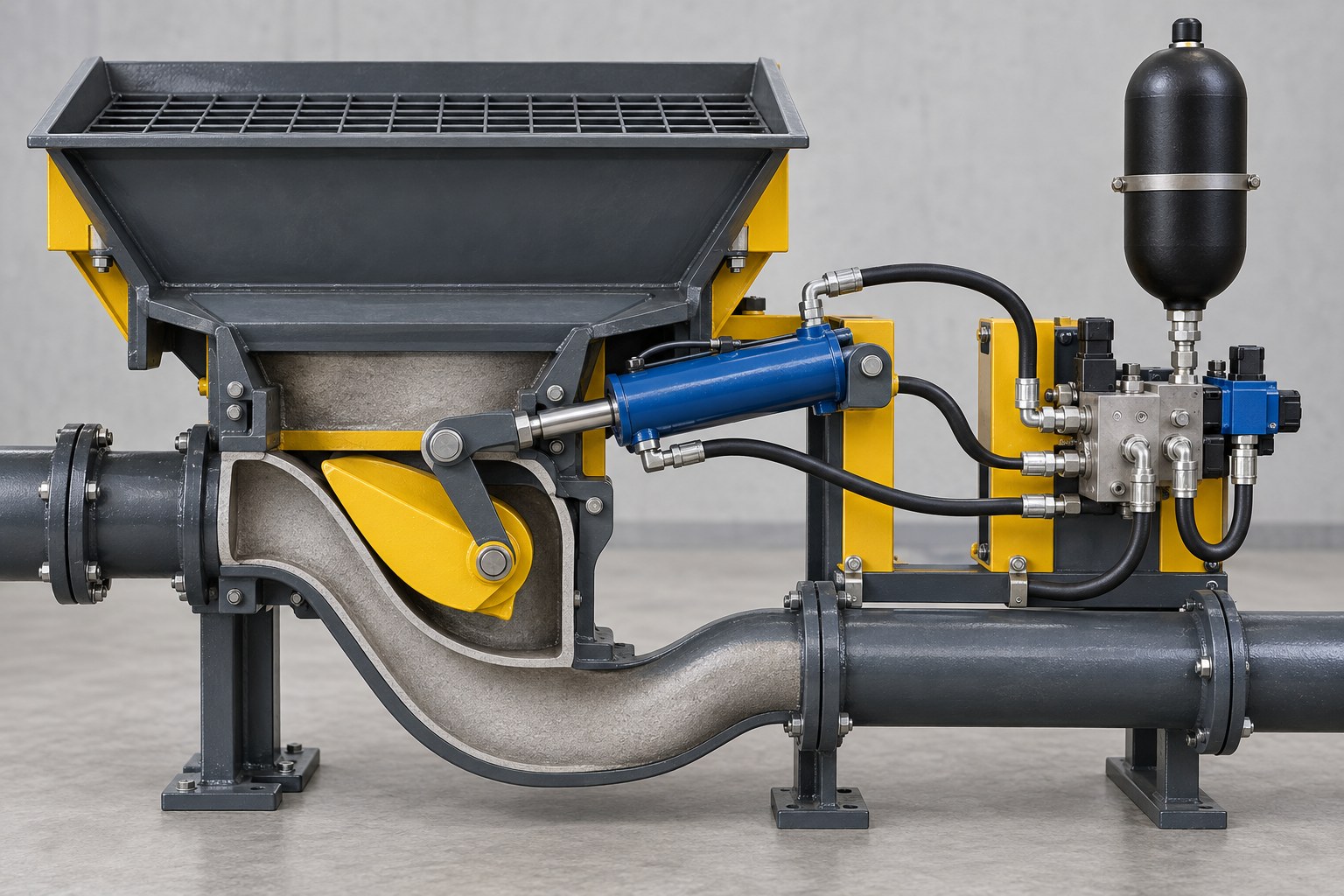
Concrete pump accumulator pressure is not one universal setting. On pumps that use a gas-charged accumulator in the S-valve or swing-tube circuit, technicians must distinguish the nitrogen precharge inside the accumulator from the hydraulic charging pressure shown while the circuit is operating. Low precharge can reduce the stored energy available for a fast, complete valve shift, but the same symptom can also come from a leaking check valve, a low hydraulic cut-off setting, internal leakage, restricted flow, or mechanical resistance at the valve.
The correct values and test method must come from the hydraulic schematic and service manual for the exact pump model. A number taken from a similar-looking machine can produce an incomplete shift, damage the bladder, or leave dangerous stored energy in the circuit.
What Does the Accumulator Do in a Concrete Pump?
In many S-valve and swing-tube concrete pumps, the accumulator stores hydraulic energy so the transfer valve can move quickly at the end of each pumping stroke. The valve must change from one delivery-cylinder opening to the other in coordination with the main pumping cylinders. A gear pump alone may not provide the required pressure and flow at the exact instant of changeover, so the accumulator supplies a short burst of pressurized oil to the shift cylinder or cylinders.
REED’s hydraulic-system description identifies the accumulator, manifold, solenoid cartridges, directional valve, check valve, and one or two shift cylinders as parts of the S-tube shift circuit. Oil enters the accumulator above the gas precharge, compresses the bladder, and remains available until the directional valve routes it to the actuator. The accumulator then recharges for the next cycle.
This architecture explains why accumulator diagnosis cannot stop at the pressure vessel. The complete energy path is:
hydraulic pump → charging and unloading controls → check valve → accumulator → directional valve → shift cylinder → lever and S-valve.
A fault anywhere in that chain can change shift speed, available force, pressure decay, or recharge behavior. The accumulator supports the Concrete Pump S-Valve Assembly; it does not independently determine whether the valve reaches its seat.
Which Accumulator Pressure Is Being Measured?
The phrase “accumulator pressure” commonly refers to three different conditions. Confusing them is one of the main reasons that otherwise accurate manual values get applied incorrectly.
| Pressure term | What it represents | Why it matters |
|---|---|---|
| Nitrogen precharge | Gas pressure on the accumulator’s gas side under the model-specified checking condition | Establishes the gas spring against which hydraulic oil is stored |
| Hydraulic charging or cut-off pressure | Upper circuit pressure at which the charging control unloads or stops adding oil | Determines how much hydraulic energy is stored before a shift |
| Live or residual gauge pressure | Hydraulic pressure observed during charging, shifting, holding, or controlled discharge | Shows circuit behavior, but it is not automatically the gas precharge |
HYDAC explains the underlying sequence: hydraulic oil enters only after system pressure exceeds precharge, compressing the nitrogen. When system pressure falls, the gas expands and pushes stored oil back into the circuit. Consequently, the running gauge can show a pressure substantially above the nitrogen precharge.
Some OEM procedures infer precharge from the hydraulic gauge while the circuit discharges. Others require a charging-and-gauging assembly on the gas valve after the hydraulic side has been isolated and depressurized. These are not interchangeable methods. A falling hydraulic gauge can be influenced by the dump valve, check valve, manifold leakage, actuator leakage, gauge response, and circuit plumbing.
Why Published Pressure Values Cannot Be Copied Between Pumps
Published OEM examples show both model variation and the difference between gas and hydraulic values. They are useful for interpretation, not as settings for an unidentified pump.
| Documented example | Gas precharge stated | Hydraulic value stated | Lesson |
|---|---|---|---|
| Mayco LS600P operating manual | 1,100 psi dry nitrogen | 1,750 psi stored-oil / gauge pressure | Precharge and running circuit pressure are different values |
| REED C90S technical manual | 1,250 psi | Model-specific circuit setting elsewhere in the manual | The manual explicitly says precharge varies among REED pumps |
| REED XXT42 technical manual | 1,305 psi | 2,755 psi S-tube shift-system pressure | A boom-pump example differs from the trailer-pump examples |
Accumulator volume, cylinder area, required oil displacement, valve mass, linkage geometry, switching time, minimum circuit pressure, pressure ratio, and allowable bladder travel all affect the design. Temperature also changes gas pressure. Even two pumps using visually similar accumulator bottles may use different precharge values, hydraulic cut-off settings, bladders, gas valves, or safety blocks.
Do not calculate a field setting from a general percentage found in an accumulator catalog. General design guidance helps engineers size a system, but an installed concrete pump already has an OEM-selected accumulator and control circuit. The serial-number-specific schematic, service bulletin, or authorized service information controls the maintenance value.
Can Low Precharge Cause a Weak or Incomplete S-Valve Shift?
Yes, low nitrogen precharge can reduce useful accumulator performance, but weak shifting does not prove low precharge. With insufficient precharge, the bladder may operate through an unfavorable volume range and the circuit pressure can fall too quickly as oil is discharged. REED’s trailer-pump training material explains that both excessive and insufficient precharge can leave the shift cylinders without the pressure-volume behavior needed for complete changeover, particularly with resistant concrete.
The observable symptom still needs to be separated from its possible mechanisms:
| Observation | Possible mechanisms | Useful verification direction |
|---|---|---|
| Accumulator charges slowly or never reaches specified cut-off | Low supply flow, pump wear, incorrect engine speed, relief or unloader fault, large leakage path | Compare charge time, supply condition, and cut-off pressure with the model manual |
| Pressure reaches cut-off but falls while the pump is not cycling | Check-valve leakage, manifold or dump-valve leakage, actuator bypass, gauge fault | Use the OEM isolation sequence to localize the loss; do not assume the bladder is leaking |
| S-valve shifts slowly in both directions | Low stored energy, restricted flow, low shift pressure, excessive mechanical resistance | Record pressure before and during shift, then inspect lubrication, buildup, wear parts, shaft supports, and linkage |
| Shift is weak in one direction | Directional-valve behavior, asymmetric restriction, hose routing, actuator leakage, linkage geometry | Compare both directions under the same safe test condition |
| Pressure behavior is normal but valve stops short | Concrete obstruction, tight wear system, incorrect cylinder adjustment, worn pins or bearings, mechanical binding | Inspect the mechanical path after full isolation and washout |
| Frequent recharge without a commanded shift | Stored-pressure leakage through a check valve, manifold, hose, or actuator | Measure the recharge interval under the exact no-cycle condition specified by the OEM |
REED’s troubleshooting guide lists low precharge, low shift-circuit pressure, unloader-manifold problems, contaminated check valves, shift-cylinder seal bypass, solenoid faults, insufficient lubrication, concrete buildup, and tight or worn valve parts as separate causes of poor S-tube shifting. This is the central diagnostic point: one symptom can cross hydraulic, electrical, and mechanical boundaries.
What Does a Pressure-Drop Test Actually Prove?
A controlled pressure-decay observation can show whether the swing circuit retains stored hydraulic pressure as expected. It cannot, by itself, identify the leaking component. A rapid drop may result from a failed bladder, but it can also result from an open dump path, leaking check valve, directional-valve leakage, damaged hose, or internal bypass in a shift cylinder.
Some concrete-pump manuals describe watching the hydraulic gauge after shutdown or after an emergency-stop function opens the dump path. In a correctly defined procedure, the point where pressure behavior changes can be used to estimate gas precharge. That inference depends on the circuit discharging in the way the manufacturer intended. If the dump valve does not operate, the gauge is inaccurate, or another leakage path dominates, the curve can be misleading.
A direct gas-side reading also has conditions. The hydraulic side must be isolated and reduced to the required state before the gas pressure is interpreted. Connecting a generic tire gauge to a charged accumulator is neither an acceptable test nor a safe substitute for the specified charging-and-gauging equipment.
Why Is Excessive Precharge Also a Problem?
Adding more nitrogen does not create an unlimited reserve of shift energy. If precharge is too high relative to the circuit’s minimum and maximum pressures, hydraulic oil may not enter in the required volume before the cut-off setting is reached. The gauge may show the expected upper pressure while the accumulator stores too little usable oil for the full cylinder stroke.
Parker’s accumulator engineering guide explains that excessive precharge in a bladder accumulator can force the bladder against the poppet assembly, while very low or absent precharge can allow damaging deformation toward the gas stem. Both conditions can reduce performance and damage the bladder. The appropriate response to suspected low pressure is therefore measurement and diagnosis—not adding nitrogen until the S-valve appears to move harder.
How Can the Accumulator Be Checked Safely?
A hydraulic accumulator remains a stored-energy device after the engine or motor stops. Before anyone enters the hopper area, disconnects a hose, removes the accumulator, or touches the gas valve, follow the exact machine lockout, discharge, restraint, and verification procedure. A stopped engine and a zero-looking main-pump gauge do not prove that every hydraulic circuit is depressurized.
A safe diagnostic plan normally separates observations that can be made without opening the circuit from specialist accumulator service:
- Identify the pump model, serial number, hydraulic schematic revision, accumulator part number, and applicable service procedure.
- Record the correct gauge, engine speed, oil temperature, operating mode, charge time, cut-off pressure, pressure immediately before shift, minimum pressure during shift, and recharge interval where the manual calls for those observations.
- Check the command and mechanical load. Confirm that the solenoid receives the intended signal and that hardened concrete, insufficient lubrication, wear-ring interference, shaft resistance, or linkage damage is not preventing travel.
- Verify the circuit’s approved pressure-release function and confirm zero residual hydraulic pressure at the specified point before service access.
- Have trained personnel use the specified charging-and-gauging equipment, regulator, adapters, and dry nitrogen if a gas-side check or correction is required.
Parker’s bladder-accumulator maintenance instructions require complete release of hydraulic pressure before removal and specify nitrogen rather than other gases. The Mayco LS600P manual likewise warns that improper charging can cause an explosion and limits the procedure to qualified personnel using dry nitrogen. Never use oxygen or compressed shop air.
How Do You Separate an Accumulator Fault From a Slewing-Cylinder Fault?
An accumulator fault affects the energy available to the circuit. A shift-cylinder fault wastes or loses that energy after it has been routed to the actuator. Pressure and motion must therefore be considered together.
If the accumulator reaches the model’s specified hydraulic cut-off and retains pressure until the shift command, yet pressure collapses with weak motion, the investigation may move toward the directional valve, flow path, actuator bypass, or excessive mechanical resistance. If the cylinder moves normally when isolated and tested by the OEM method but the circuit cannot retain stored pressure, a check valve or manifold leakage path becomes more plausible. These are diagnostic directions, not universal pass/fail rules.
When internal leakage in Concrete Pump Slewing Cylinders is suspected, inspect the rod, gland, mountings, pins, hoses, and alignment as well as the piston seals. Replacing the cylinder will not correct an unloader setting, failed accumulator bladder, open dump valve, or S-valve binding. Recharging the accumulator will not correct cylinder bypass or a worn mechanical connection.
What Information Is Needed Before Ordering an Accumulator or Bladder?
Do not order from appearance alone. Accumulators are pressure vessels, and interchangeability depends on more than overall size. Provide:
- pump manufacturer, exact model, serial number, year, and hydraulic-schematic revision;
- OEM accumulator and bladder part numbers plus a clear nameplate photograph;
- accumulator type, nominal volume, maximum working pressure, and approved temperature range;
- gas-valve type, hydraulic port, mounting orientation, clamp locations, and available envelope;
- specified nitrogen precharge, reference temperature, and checking condition;
- hydraulic cut-in, cut-off, relief, and minimum shift pressures when documented;
- hydraulic-fluid type and required bladder/elastomer compatibility;
- observed charge time, decay pattern, shift symptom, and any known contamination or overheating event.
When considering only a bladder or seal kit, confirm the accumulator series, shell size, fluid compatibility, gas-valve design, poppet components, and current manufacturer instructions. A dimensionally similar bladder made from the wrong compound can be incompatible with the fluid or temperature range.
Common Questions About Concrete Pump Accumulator Pressure
Does a zero hydraulic gauge mean there is no nitrogen in the accumulator?
No. A hydraulic gauge can read zero after the oil side is discharged while the gas bladder remains precharged. Gas pressure and residual hydraulic pressure are different conditions, and both must be handled according to the service procedure.
Can the accumulator be recharged whenever the S-valve shifts slowly?
No. First verify the specified precharge condition and rule out low hydraulic charging pressure, leakage, restricted flow, control faults, and mechanical resistance. Charging without a valid measurement can create excessive precharge and reduce usable oil volume.
Can pressure be checked when the oil is hot?
Gas pressure changes with temperature. Record temperature and follow the OEM or accumulator manufacturer’s correction method. A hot reading should not be compared directly with a cold specification unless the procedure explicitly allows it.
How often should precharge be checked?
Use the interval in the pump and accumulator documentation, then shorten it if trend data, severe cycling, temperature, permeation, or repeated shift faults justify closer monitoring. There is no single interval for every pump. A maintenance record is more useful than repeated undocumented top-ups.
Conclusion
Concrete pump accumulator diagnosis starts by naming the pressure correctly. Nitrogen precharge, hydraulic cut-off pressure, and the live gauge reading describe different states of the swing circuit. Low precharge can weaken S-valve changeover, but so can stored-pressure leakage, low supply, a control fault, actuator bypass, or mechanical binding.
Use the exact pump schematic, record pressure and motion under defined conditions, verify stored-energy isolation, and reserve gas-side service for trained personnel with the correct equipment and dry nitrogen. That approach protects both technicians and parts budgets while producing evidence strong enough to decide whether the accumulator, manifold, shift cylinder, or valve mechanism actually needs attention.
Technical References
- Multiquip Mayco LS600P operation manual, accumulator circuit, checking pressure, safety, and troubleshooting sections.
- REED trailer concrete pump training manual, accumulator charging states and effects of high or low precharge.
- REED C90S technical manual, S-tube circuit and model-specific accumulator description.
- REED concrete pump hydraulic-system description, S-tube shift-circuit sequence and components.
- Parker, Making the Choice—Accumulators, precharge effects, temperature, and bladder-failure mechanisms.
- HYDAC hydraulic accumulator FAQs, operating principle, mounting, material compatibility, and repair-kit identification.