Concrete Pump Parts Knowledge
Concrete Pump Agitator Shaft Seals: Leak Diagnosis and Ordering Checks
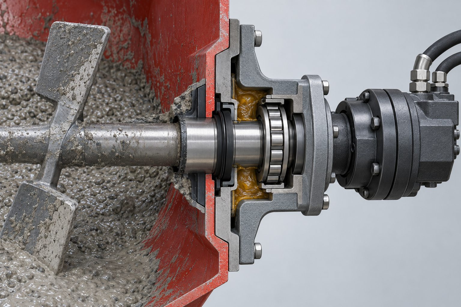
A concrete pump agitator shaft seal should keep abrasive cement paste away from the shaft support while allowing the shaft to rotate and receive lubrication. Leakage at this point is rarely solved by choosing a rubber ring from diameter alone. Slurry outside the hopper may come from a worn concrete-side seal, but it can also reflect a grooved shaft, bearing play, a distorted housing, a blocked grease path, or a leaking hydraulic motor. The repair decision therefore starts with identifying which side of the assembly is leaking and which parts actually locate the shaft.
This article focuses on the hopper agitator, also called the remixer on some trailer pumps. It does not cover the moving face seal between a cutting ring and wear plate, the outlet seal of an S-tube, or the internal shaft seal of the agitator hydraulic motor. Those parts work in the same general area, but their leak paths and ordering data are different.
What does the agitator shaft seal protect?
The agitator shaft passes through the hopper wall, so its support must separate two incompatible environments. Inside the hopper are wet concrete, aggregate, cement paste, wash water, and hardened residue. Outside are the bearing support, coupling, hydraulic motor, and lubrication hardware. The shaft seal is the first barrier, but it cannot hold the shaft concentric by itself. Bearings, bushings, wear rings, flanges, or sleeves establish the running geometry, depending on the machine.
OEM parts books show why “agitator seal kit” is not a universal description. A current REED B50HPSC manual lists a flange seal, a remixer seal, two different bearings, an agitator wear ring, a shaft, a grease fitting, and a separate hydraulic-motor seal kit. A Mayco LS600 parts book uses another arrangement: a remixer shaft, follower rings, multiple graphite packing rings, compression springs, a shaft-support bearing, a housing, and a drive coupling. The seal concept, part count, and service method are model-specific.
This distinction matters commercially. A buyer who asks only for a “mixer shaft seal” may receive the hopper-side packing, the hydraulic-motor repair kit, or a collection of O-rings for an unrelated flange. The words seal, gasket, packing, scraper, dust seal, remixer seal, and agitator seal are not interchangeable unless the corresponding drawing confirms their location.
Which leak are you actually seeing?
| Observation | Possible mechanism | What to verify before ordering |
|---|---|---|
| Cement paste or wash water appears at the hopper-wall shaft opening | Concrete-side seal or packing has lost contact; the shaft or sleeve may be grooved; shaft movement may be opening the sealing line | Leak origin after cleaning, shaft surface, radial play, housing condition, seal orientation, and grease path |
| Grease purges toward the hopper but quickly becomes gray or gritty | The purge path is open, but contamination is reaching the lubricated cavity | Whether the discharge is fresh grease, diluted grease, cement paste, or wash water; inspect the inboard sealing surface |
| Grease enters the fitting but no purge appears at the expected location | Blocked passage, displaced seal, hardened grease, or an incorrect assumption about the designed purge point | OEM lubrication diagram and passage continuity; do not infer flow from gun resistance alone |
| Shaft or paddle can be moved radially by hand after safe isolation | Bearing, bushing, flange, shaft journal, or fastener wear | Measure play at the shaft and identify where movement begins; a new soft seal will not restore alignment |
| Hydraulic oil appears between the motor and its mounting flange | Hydraulic-motor shaft seal or motor housing leak rather than a concrete-side agitator seal | Oil identity, motor model, case-drain condition if applicable, and motor repair instructions |
| Agitator slows, stalls, or runs unevenly | Mechanical binding, hardened concrete, bearing damage, coupling/key failure, restricted hydraulic flow, or motor fault | Mechanical freedom after isolation, coupling and key, hydraulic supply, and the manufacturer’s troubleshooting sequence |
These observations narrow the investigation; they do not prove one root cause. REED’s trailer-pump troubleshooting guidance, for example, lists a frozen idler pin, broken or missing drive connection, broken key, absent hydraulic flow, control-valve faults, and motor faults as possible causes when the remixer will not rotate. A seal should not be blamed until the drive and support system have been separated logically.
Why can a new agitator seal leak again?
The shaft no longer provides a usable running surface
A sealing lip or packing ring needs a surface that is round, reasonably concentric, and free from a deep wear groove in its contact band. Abrasive paste can reach the shaft, while a rotating seal can polish or groove the same track over time. Installing a new seal on that track may restore contact briefly, but the damaged surface can cut the lip, create a bypass path, or produce uneven loading.
Inspect the entire sealing band rather than one convenient diameter. Record groove depth, corrosion, scoring, step wear, and the location of the contact track. If the design uses a replaceable sleeve, identify it separately. Do not assume that moving the seal axially or polishing the shaft is an approved repair; either action can change contact with shoulders, spacers, or grease passages.
Bearing play moves the shaft away from the seal
A seal is not a bearing. When the shaft moves radially, its centerline changes relative to the seal housing. The sealing element is then compressed on one side and unloaded on the other. The result may be an intermittent slurry trace that becomes worse when the paddles are loaded by concrete. Uneven wear around the seal, a polished eccentric band, or repeat failure soon after installation should prompt a bearing and housing inspection.
The support arrangement may not be symmetrical. The REED parts diagrams distinguish a plain bearing from a one-seal bearing, while the Mayco LS600 arrangement uses a packing stack and a separate shaft-support bearing. Copying the sequence from a different model can therefore create the wrong preload, wrong sealing direction, or wrong spacing even when several parts appear to fit.
Lubricant is not reaching the intended cavity
Grease can provide lubrication and, in some designs, help purge contaminants away from the bearing zone. It cannot rebuild a worn shaft or correct a loose bearing. A grease gun becoming hard to operate is not evidence that the cavity is full; it may indicate a blocked fitting or passage. Conversely, grease emerging somewhere near the shaft does not prove that it crossed every intended interface.
Use the lubrication map for the specific pump. A REED B70 manual identifies three agitator/remixer grease points—two on the non-motor end and one on the motor end—and specifies a model-specific interval and lubricant. Putzmeister’s P715 operating manual tells operators to check the bearings and seals on the agitator shaft regularly and lubricate as required. These examples establish the importance of the path, but they are not universal instructions for another machine.
Installation changed the seal geometry
A reversed lip, pinched packing ring, damaged edge, missing spacer, uneven follower compression, or cocked flange can create immediate leakage. On a packing-style arrangement, the order and quantity of rings, follower components, and springs are part of the design. On a lip-seal arrangement, direction may determine which side is excluded or retained. Record the as-removed sequence before cleaning, then compare it with the current serial-number-specific drawing.
Fastener torque, packing compression, seal lubricant, and adjustment method must come from the applicable manual. Applying a convenient generic torque or tightening a follower until leakage stops can overheat the shaft, overload the support, or conceal a geometry problem.
How should the assembly be inspected safely?
The hopper contains severe entanglement, crushing, and amputation hazards. Before touching the agitator, follow the pump manufacturer’s shutdown and lockout procedure, isolate the hydraulic system, and verify stored energy is removed. The American Concrete Pumping Association’s mechanics guidance specifically says not to work in the hopper or on the agitator unless the engine is shut off or the truck is out of gear and zero accumulator pressure has been verified. A stationary paddle and an activated emergency stop are not, by themselves, proof of zero energy.
- Preserve the evidence. Photograph the leak before washing. Note whether the material is cement paste, watery slurry, clean grease, contaminated grease, or hydraulic oil.
- Identify the side and component. Mark the motor end and support end. Record the motor plate, pump model, serial number, hopper or assembly number, and any casting or part numbers.
- Check shaft support. With the machine safely isolated, evaluate radial and axial movement using the OEM method. Note whether movement originates in the bearing, housing, coupling, or shaft joint.
- Open without erasing the sequence. Photograph each layer as it is removed. Keep spacers, followers, springs, seals, and bearings in order.
- Inspect hard parts. Examine the shaft or sleeve, seal bore, bearing seat, flange face, fastener holes, grease passages, coupling, key, and hopper-wall mounting surface.
- Compare both ends. Some pumps use different parts or lubrication arrangements at the motor and non-motor sides. Do not assume mirror-image stacks.
Cleaning is necessary for measurement, but aggressive scraping can destroy the leak track or damage a sealing surface. Remove hardened concrete using the procedure approved for the machine and the component material. Never rotate the agitator under power while someone is observing an exposed shaft or open hopper area.
Can the seal be replaced without replacing the shaft or bearing?
Yes, but only when the sealing surface, support geometry, housing, and lubrication path remain serviceable. A seal-only repair is a defensible choice when the shaft has no unacceptable groove or corrosion, measured play is within the manufacturer’s limit, the bearing turns and locates correctly, the housing is undamaged, and the leak can be traced to the sealing element or its installation.
Broaden the repair scope when the shaft has a deep contact groove, the bearing allows measurable misalignment, the seal bore is distorted, the flange is loose, grease passages are blocked, or slurry has reached the bearing. If the hydraulic motor is leaking oil at its shaft, the required kit may belong to the motor rather than the hopper-side seal stack. These decisions should follow the OEM limits; there is no reliable universal clearance or groove-depth threshold for every concrete pump.
What information should a buyer send for a quotation?
A useful RFQ identifies the leak path and the surrounding hard parts, not just a nominal shaft diameter. Include:
- pump manufacturer, model, serial number, and year or configuration;
- hopper, remixer, or agitator assembly part number when available;
- motor-end or non-motor-end location;
- hydraulic motor manufacturer, model, shaft form, and mounting pattern if the motor side is involved;
- all readable part numbers from seals, bearings, wear rings, sleeves, followers, and housings;
- clear photos of the installed assembly, both hopper sides, the removed sequence, and the shaft contact band;
- shaft diameter at unworn and worn locations, housing bore, overall stack length, and relevant flange dimensions;
- observed radial or axial movement and how it was measured;
- whether the leak is concrete slurry, grease, wash water, or hydraulic oil;
- the required scope: soft seals only, seal-and-bearing kit, shaft or sleeve, complete support, coupling, or motor kit.
Keep original drawing units and precision. If an inch dimension is recorded as 1.250 in, preserve all three decimal places before converting it to millimetres; the converted value is 31.750 mm. Do not round the inch value first. Also distinguish measurements taken from a worn part from the specified new-part dimension.
The agitator shares the hopper environment with the Concrete Pump S-Valve Assembly, but the two seal systems should be quoted separately unless the overhaul scope genuinely includes both. Likewise, poor material feed near the inlet may affect the fill of the Concrete Pump Delivery Cylinders; that operational relationship does not make the agitator seal part of a delivery-cylinder kit.
What should be checked after reassembly?
Before adding concrete, confirm that guards and interlocks are restored, fasteners and hydraulic connections meet the manufacturer’s requirements, the shaft turns without abnormal drag under the approved test procedure, and lubricant reaches the specified point. During the controlled functional check, watch from a safe position for eccentric motion, unusual noise, heat, oil leakage, or seal displacement.
After the first operating period, inspect the external leak path again. A small amount of fresh purge grease may be expected on some designs; cement-contaminated grease, renewed shaft play, heat, or a growing slurry trail calls for shutdown and reinspection. Do not use repeated greasing as a substitute for correcting damaged geometry.
Conclusion
Concrete pump agitator shaft seal leakage is a system condition, not automatically a rubber-part failure. The reliable diagnosis separates concrete-side contamination from hydraulic oil, checks the shaft and support before blaming the seal, verifies the actual grease route, and preserves the model-specific assembly sequence. That approach prevents a common purchasing error: ordering a seal that fits the diameter but cannot survive the existing wear, play, or misalignment.
Technical sources
- REED B50HPSC Technical Manual — agitator assembly parts and separation of hopper-side seals, bearings, wear ring, shaft, and motor seal kit.
- REED B70 Technical Manual — agitator/remixer lubrication-point locations and model-specific lubrication guidance.
- Multiquip Mayco LS600 Parts Manual, Rev. 7 — remixer shaft, packing rings, follower rings, springs, bearing, housing, and coupling arrangement.
- Putzmeister P715 Operating Manual — monitoring of agitator-shaft bearings and seals and lubrication during operation.
- ACPA Safety Procedures for Concrete Pump Mechanics — hopper/agitator lockout, zero accumulator pressure, and hydraulic safety.