Concrete Pump Parts Knowledge
Concrete Pump Hydraulic Oil Filters: Bypass Warnings and Replacement Checks
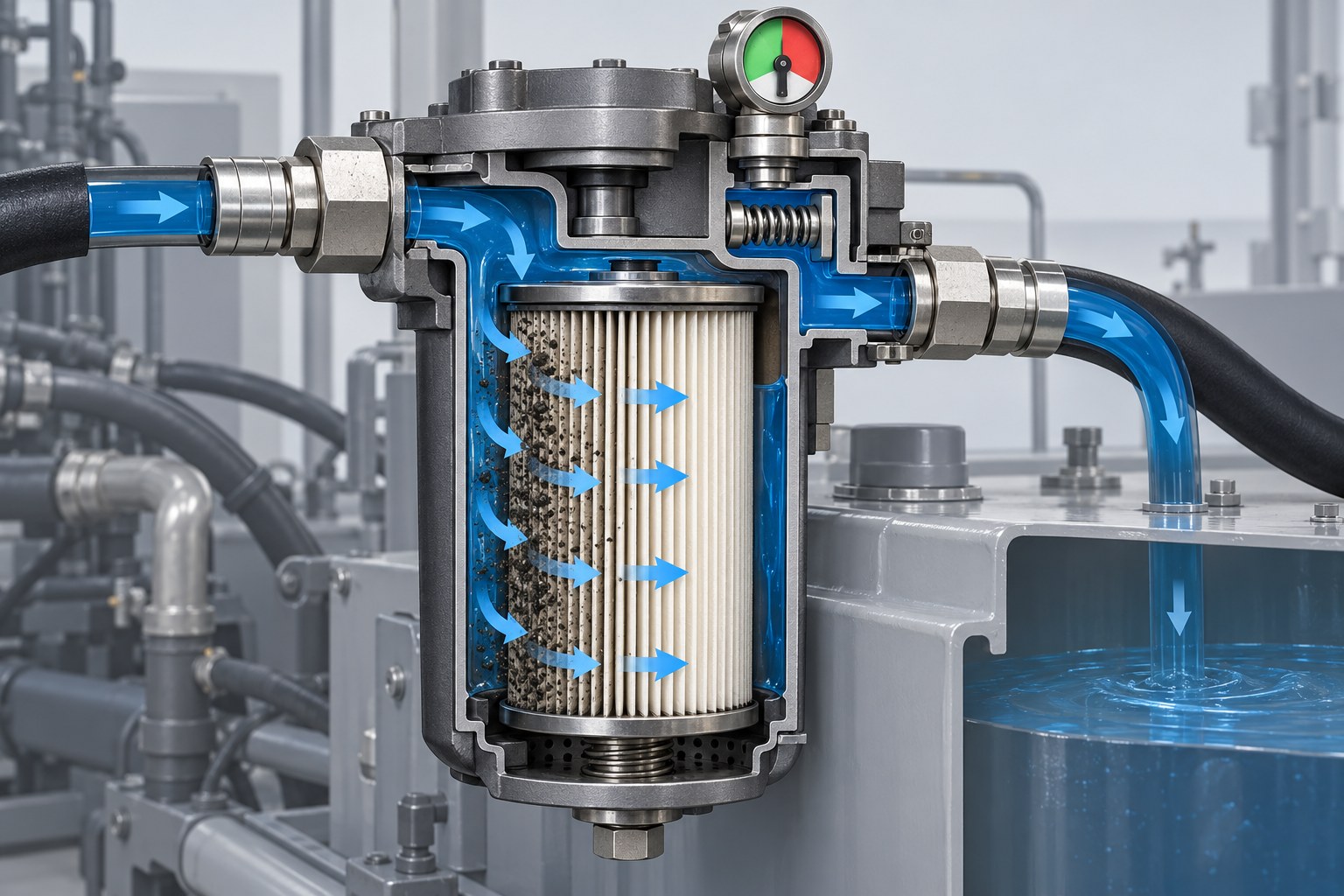
A concrete pump hydraulic filter warning usually means the pressure difference across a filter has risen—not that a sensor has counted dirt particles. Cold, viscous oil can create a temporary warning, while a warning that remains after the hydraulic system reaches the model’s specified checking condition can indicate a restricted element, an incorrect replacement element, abnormal flow, or an indicator fault. The correct response is to identify the filter circuit, confirm the oil condition and operating state, and match the replacement by more than external dimensions.
This distinction matters because a concrete pump may contain several filtration devices serving different functions: a tank breather, a return-line filter, suction strainers, charge- or loop-circuit filters, and high-pressure filters. A part described simply as a “concrete pump oil filter” may belong to the engine, hydraulic reservoir, boom circuit, or another subsystem. Installing an element that fits the housing does not prove that its efficiency, pressure-drop behavior, collapse strength, seals, or bypass arrangement is correct.
What Does a Concrete Pump Hydraulic Filter Indicator Measure?
Most service indicators infer filter condition from restriction. A differential indicator compares pressure upstream and downstream of the element; some low-pressure return-filter indicators measure inlet pressure relative to the reservoir. As the media captures contamination, resistance to flow normally increases. The indicator changes state when the pressure difference reaches its calibrated point.
The indicator therefore reports a hydraulic condition, not a direct cleanliness measurement. The same signal can be produced by a loaded element, oil that is unusually viscous, excessive flow through the housing, a damaged line, a wrong element, or a defective indicator. Donaldson’s hydraulic-filter replacement guide explains that excessive restriction can open a bypass during a cold start, pressure spike, or heavy element loading, and warns that the replacement must match the required pressure, efficiency, and bypass design.
Concrete-pump manuals add an important qualification: check conditions are model-specific. A REED-hosted concrete pump manual, for example, instructs the technician to evaluate the hydraulic-filter indication with the oil above a stated temperature and the pump operating at specified speed and stroke conditions. That temperature and procedure belong to that documented machine; they should not be copied to a different pump without its OEM instruction.
Why Can the Warning Appear During a Cold Start?
Oil viscosity rises as temperature falls. Thicker oil requires a larger pressure difference to pass through the same media at the same flow. A cold-start warning that clears as the oil warms can therefore reflect viscosity rather than a dirt-loaded element.
That does not mean every cold warning is harmless. A partly loaded element has less pressure-drop margin and may reach the indicator threshold sooner or remain restricted longer. Oil of the wrong viscosity, an undersized substitute element, or an obstructed return path can produce a similar pattern. Record when the warning appears, the ambient and oil conditions, the function being operated, engine speed, and whether the warning clears under the OEM’s prescribed test condition. Timing is diagnostic evidence.
What Happens When a Filter Goes Into Bypass?
A bypass valve protects hydraulic flow when restriction becomes excessive, but oil travelling through that path is not being filtered by the element. Depending on the design, the valve may be in the filter head, housing, or element. Some high-pressure circuits intentionally use a no-bypass arrangement. This is why “same size” and “same micron number” are inadequate replacement criteria.
A bypass valve is not the same as an offline or kidney-loop filter. The first is a pressure-responsive alternate flow path around the main element. The second is a separate filtration circuit used to clean reservoir oil. Confusing those meanings can lead to an incorrect diagnosis or purchase.
The bypass setting must coordinate with the housing, element strength, flow range, oil viscosity, and indicator setting. Do not alter a spring, drill a valve, omit a bypass component, or substitute a no-bypass element by assumption. The correct arrangement is defined by the pump and filter manufacturer.
Return, Pressure, Suction, and Breather Filters Are Not Interchangeable
| Filter location | Primary job | Common diagnostic trap | Ordering evidence |
|---|---|---|---|
| Return line | Captures contamination before oil re-enters the reservoir | Cold or peak return flow is mistaken for a permanently clogged element | Housing and element numbers, maximum return flow, indicator and bypass data |
| High-pressure line | Protects a sensitive downstream circuit | A return-filter element is selected because the dimensions appear similar | Pressure rating, collapse rating, circuit location, media and seal specification |
| Suction strainer/filter | Stops large debris before the pump inlet, depending on design | Excessively fine or restricted media starves the pump and is misdiagnosed as pump failure | Strainer type, mesh or element designation, inlet layout, OEM service instruction |
| Reservoir breather | Filters air entering as reservoir level changes | The breather is omitted from a contamination investigation because it does not carry oil flow | Cap or breather part number, filtration and moisture-control features if specified |
| Loop or charge circuit | Maintains cleanliness in a closed or semi-closed hydraulic circuit | The element is grouped with the main return filter although its service and bleeding procedure differs | Hydraulic schematic, filter location, OEM element number and recommissioning method |
The REED C50 concrete pump manual documents a return filter on top of the hydraulic tank, an indicator gauge, tank breathers, magnetic suction strainers, and an oil cooler as separate components. The Multiquip Mayco LS600P hydraulic schematic likewise identifies the return filter within a specific circuit. These examples show why the machine schematic and parts manual should be consulted before naming the element.
A Practical Diagnostic Workflow for a Filter Warning
1. Make the machine safe before opening the system
Stop pumping, isolate energy, and follow the manufacturer’s lockout and pressure-release procedure. A stopped engine does not prove every accumulator or line is depressurized. Hot oil can burn, and a pressurized leak can penetrate skin. The American Concrete Pumping Association mechanics guide states that work must not be performed on a pressurized hydraulic system and emphasizes zero accumulator pressure for relevant pump maintenance.
2. Identify the exact warning and filter circuit
Photograph the display message or indicator position. Locate the filter on the hydraulic schematic. Determine whether the device is visual, electrical, pressure-based, vacuum-based, or differential. Confirm whether the indicator is temperature-inhibited by the control system. Do not assume a red indicator on one housing reports every hydraulic filter on the machine.
3. Compare cold and warmed behavior under the correct test condition
Record oil temperature if the machine provides it, ambient conditions, engine speed, pumping rate, and the hydraulic function being used. If the warning clears only at low speed but returns during normal pumping, the difference may be related to flow as well as contamination loading. Use the OEM procedure; do not heat the machine by operating against relief or by creating an artificial load.
4. Check conditions that can raise restriction
Verify the specified hydraulic-fluid grade and reservoir level from the machine documentation. Inspect for kinked hoses, damaged filter heads, closed service valves, incorrect plumbing after repair, and a breather that is blocked or improperly substituted. Review recent work: a new hose, cylinder, valve, cooler, or reservoir repair can introduce contamination, while an incompatible seal or media can cause a new restriction problem.
5. Replace the element cleanly and investigate unusual loading
Clean the exterior before opening the housing. Prevent dirt, lint, water, old gasket material, or packaging debris from entering. Retain every bypass component, spring, standpipe, O-ring, and anti-drain part in the documented sequence. Lubricate seals only with the approved clean fluid and follow the specified tightening and bleeding procedure.
A heavily loaded or damaged element is evidence, not just waste. Note metallic particles, rubber fragments, collapsed pleats, water, sludge, or unusual odor. Do not cut open a pressure element casually or return debris to the circuit. If contamination is abnormal or a replacement plugs quickly, oil sampling and a root-cause investigation are more useful than repeatedly installing elements.
What Must Be Confirmed Before Ordering a Replacement?
Marketplace listings commonly mix “suction,” “return,” “boom,” “main,” and “hydraulic oil” filter terminology. Listings are useful for finding possible part-number families, but their unverified micron, pressure, temperature, and compatibility claims should not replace OEM or filter-manufacturer data.
- Pump identity: manufacturer, model, serial number, year, and hydraulic-system variant.
- Filter location: return tank, high-pressure line, suction side, loop/charge circuit, breather, or another circuit.
- Existing identifiers: complete element number, housing number, head number, and any superseded OEM number.
- Element construction: length, outside and inside diameters, end-cap geometry, center tube, seal position, and installed orientation.
- Performance data: rated flow, filtration ratio/efficiency, contaminant capacity, clean pressure drop, terminal pressure drop, and collapse rating where applicable.
- Bypass arrangement: valve in the head, housing, element, or no bypass; required setting and indicator relationship.
- Fluid and seals: approved hydraulic fluid and seal material compatibility.
- Operating conditions: expected temperature/viscosity range and peak—not merely average—flow.
ISO 16889:2022 defines a multi-pass test for determining particulate removal, contaminant capacity, and differential-pressure characteristics of hydraulic filter elements. An ISO 16889 result provides a comparative test basis; it is not proof that any element with an attractive “micron” label is compatible with a particular concrete pump.
Is a Finer Hydraulic Filter Always Better?
No. Finer media may remove smaller particles, but the element must still carry the required flow across the specified viscosity range without excessive pressure drop. It also needs adequate dirt capacity and structural strength. A substitute that begins life too close to the indicator or bypass threshold may spend substantial time in bypass, collapse, or create an operating restriction even though its nominal filtration claim sounds superior.
Filter efficiency should also be stated clearly. A bare micron value may be nominal, absolute, or marketing language. Ask for the tested filtration ratio and test standard, not only a pore-size claim. The replacement decision is a system-matching exercise.
Can a Clogged Filter Explain Slow or Erratic Pump Operation?
It can contribute, but the symptom is not specific. A restricted suction path can starve a pump; a return restriction can increase backpressure; bypassed or poorly filtered oil can accelerate contamination-related wear. Yet slow cycling, heat, noise, or unstable S-valve movement may also result from fluid level, aeration, pump wear, relief-valve leakage, valve faults, electrical controls, accumulator condition, or internal cylinder leakage.
Do not condemn a hydraulic component from a filter warning alone. For example, contamination can affect the valves and actuator surfaces that control Concrete Pump Slewing Cylinders, but hot oil or a restriction alert does not by itself prove that the cylinder seals are bypassing. Confirm the filter condition first, then continue with pressure, flow, electrical, and leakage tests specified for the machine.
Why Does a New Filter Warning Sometimes Return Quickly?
A rapidly recurring warning can indicate the wrong element, cold oil, an indicator or bypass fault, residual contamination after a component failure, debris released during hose or reservoir work, deteriorating elastomer, water-related sludge, or continuing internal wear. It can also occur when the housing is undersized for an altered circuit or when a replacement line changes return-flow restriction.
Record the removed element number and condition, verify the new element against the housing, and inspect upstream repairs. Where justified, obtain an oil sample before draining or topping up so the laboratory result represents the operating fluid. Replacing filters repeatedly without preserving evidence makes the root cause harder to identify.
Conclusion
A concrete pump hydraulic filter warning is best treated as a restriction signal that requires context. First identify the circuit and indicator type. Then compare cold and warmed behavior using the OEM test condition, check oil and flow-related causes, and replace the element with contamination control. For purchasing, match the housing, circuit, filtration performance, pressure-drop behavior, bypass arrangement, structural rating, seals, and exact machine configuration. That process protects the hydraulic system more reliably than choosing by dimensions or a micron number alone.