Concrete Pump Parts Knowledge
Concrete Pump Hydraulic Oil Overheating: Causes and Diagnostic Workflow
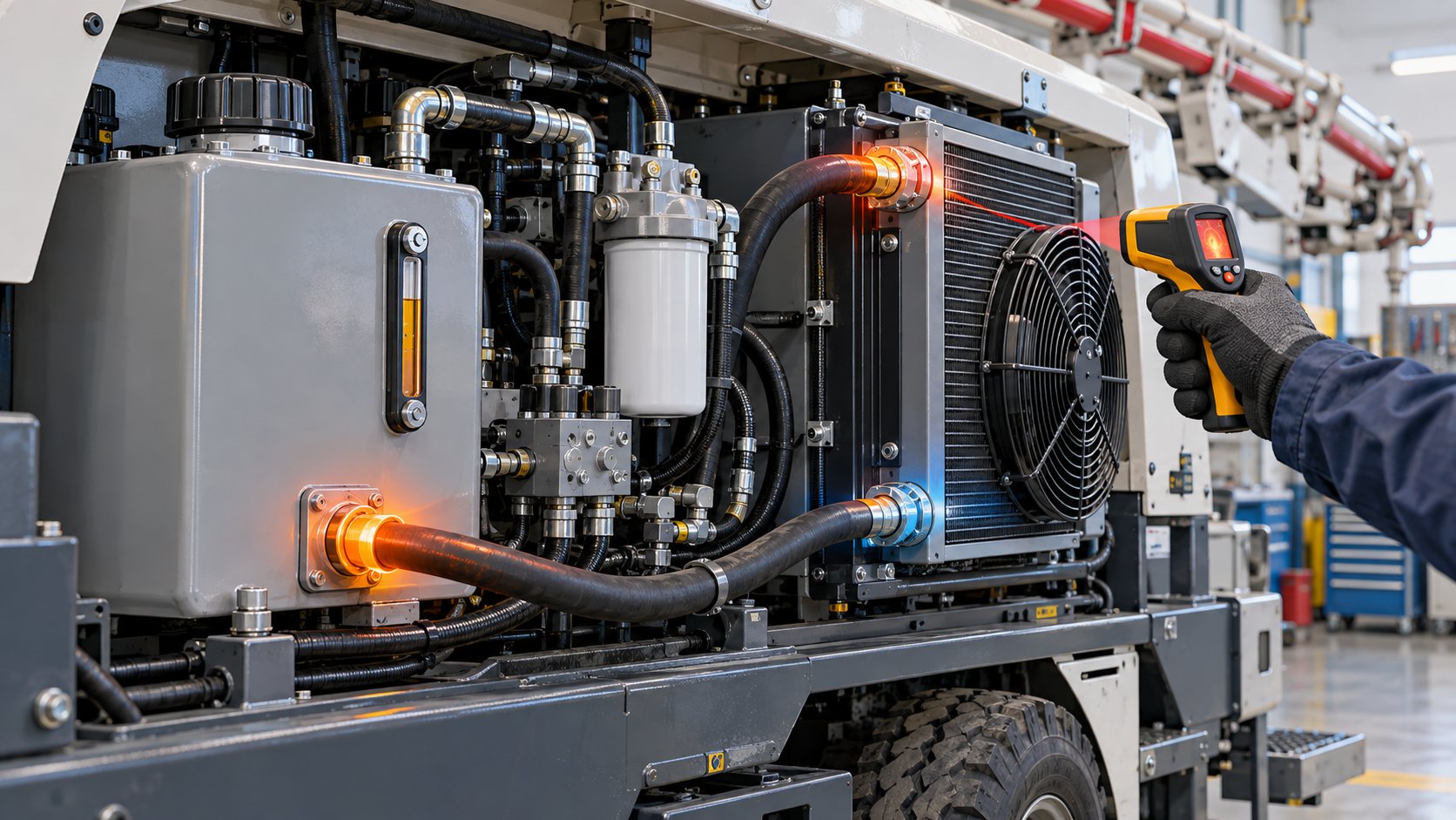
Concrete pump hydraulic oil overheating is a symptom, not a diagnosis. The temperature can rise because the cooler is unable to reject normal heat, because the hydraulic circuit is converting too much power into heat, or because both conditions occur together. A clean-looking radiator does not prove that the cooling system works, and a running fan does not prove that oil is flowing through the cooler.
The practical way to diagnose an overtemperature warning is to record when it occurs, confirm the reading, then separate heat-rejection faults from heat-generation faults. This article provides that sequence without assuming a universal temperature limit, relief setting, oil grade, or cooler specification. Those values must come from the manual for the exact pump model.
Why does hydraulic oil overheat in a concrete pump?
A hydraulic system produces heat whenever power is lost instead of being converted into useful actuator motion. Oil passing across a restriction or relief valve, internal leakage across worn clearances, and sustained high-pressure operation all dissipate energy as heat. The reservoir, cooler, airflow, and surrounding structure must then remove that heat fast enough to reach a stable operating temperature.
Overheating therefore has two broad root-cause groups:
- Insufficient heat rejection: restricted cooler airflow, a fan that does not start or rotates incorrectly, hot-air recirculation, low oil level, restricted return flow, or a cooler circuit that is not receiving the intended oil flow.
- Excessive heat generation: prolonged high-pressure pumping, a blocked agitator, a relief or pressure-reducing valve passing oil unnecessarily, internal leakage, a clogged filter or strainer, or mechanical resistance that makes an actuator work harder.
Concrete-pump OEM troubleshooting information supports this distinction. The REED trailer-pump troubleshooting guide lists restricted cooler airflow, fan faults, clogged filters and strainers, incorrect relief-valve behavior, low oil level, and extended high-pressure operation among the checks for hot hydraulic fluid. The Multiquip Mayco LS300P operation manual likewise separates fan and cooler-fin faults from return-filter, relief-cartridge, and oil-level causes.
Do not begin by replacing the oil cooler
If the reservoir becomes hot, the cooler is an obvious suspect, but it is only one part of the thermal balance. Replacing it before checking the duty cycle and hydraulic load can leave the heat source untouched. Conversely, adjusting a relief valve cannot restore airflow through a cooler packed with cement dust.
The timing of the temperature rise is often more informative than the peak number:
| Observation | What it may suggest | What to verify next |
|---|---|---|
| Temperature rises during nearly every function, including light operation | Low oil level, poor airflow, fan fault, hot-air recirculation, measurement error, or a system-wide restriction | Oil level and condition, fan command and direction, cooler cleanliness, filter indicator, and actual temperature at repeatable points |
| Temperature rises mainly during high-output or high-pressure pumping | Normal load may be exceeding available cooling, or the pump may be operating against abnormal concrete or pipeline resistance | Compare the event with pumping pressure, output setting, line configuration, mix behavior, and OEM duty limits |
| Temperature rises while the agitator is stalled or held against resistance | Continuous pressure loss across the agitator circuit can be generating heat | Stop the condition; inspect the mechanical obstruction and the model-specific control/relief circuit |
| Fan runs, but cooler inlet and outlet temperatures show little useful difference | Low cooler flow, bypass operation, internal fouling, insufficient airflow, or a measurement problem | Confirm the cooler circuit and test method from the hydraulic schematic; do not infer flow from fan noise alone |
| Oil heats after a recent repair | Wrong oil, incorrect level, reversed fan wiring, a closed valve, kinked hose, wrong filter, misadjustment, or plumbing error | Compare the as-built condition with the schematic, service procedure, part numbers, and pre-repair records |
| One function is slow or weak before the temperature alarm appears | That circuit may have internal leakage, binding, restriction, or unintended relief flow | Isolate the affected function with approved pressure, flow, leakage, and mechanical checks |
These observations narrow the investigation; none proves a root cause by itself. For example, a small temperature difference across a cooler can mean poor heat transfer, but it can also occur when little oil flows through the cooler or when the measurements are taken at inconsistent surfaces.
First confirm that the oil is actually too hot
Start with the machine’s displayed temperature or warning, then verify it with the procedure and measuring location specified by the manufacturer. An infrared thermometer can be useful for comparisons, but reflective fittings, paint color, distance, viewing angle, and emissivity can distort surface readings. Contact probes or installed sensors may be more suitable where the service procedure calls for them.
Record at least:
- ambient temperature and whether the pump is in sun or an enclosed area;
- oil temperature at a repeatable location;
- time from cold start to the warning;
- pumping output setting and indicated hydraulic pressure;
- pipeline diameter, length, elevation, reducers, and recent configuration changes;
- concrete behavior and whether a blockage or severe restriction was suspected;
- which functions were being used immediately before the rise; and
- fan start behavior, direction, and whether discharged hot air returns to the cooler intake.
Do not transplant a shutdown threshold from another pump. One REED-hosted boom-pump manual describes a model-specific thermostat and automatic stop sequence, while other machines use different sensors, limits, and control logic. Treat the installed pump’s manual and data sheet as the authority.
Check the heat-rejection side
1. Oil level and reservoir condition
Low oil level reduces the thermal mass available to absorb and reject heat and can expose the suction circuit to aeration. Check the level only under the conditions stated by the OEM, because cylinder position and oil temperature can change the sight-gauge reading. Foaming or persistent bubbles indicate a different problem from simple low level and should prompt inspection for air entry, return-line disturbance, or unsuitable fluid handling.
2. Cooler fins, guards, and airflow path
Inspect both faces of the cooler, not just the visible side. Cement dust, fibers, plastic film, leaves, and oily dirt can bridge the fin passages. Also inspect screens and adjacent radiators that share the airflow path. Cleaning method and pressure must follow the manufacturer’s instructions; crushed fins can reduce airflow even after the dirt is gone.
Confirm that the fan starts at the intended condition, reaches normal speed, and turns in the correct direction. A fan can sound normal while moving air the wrong way after electrical work. Check whether engine exhaust or hot compartment air is being drawn back through the cooler. REED specifically includes restricted airflow, enclosure ventilation, fuse and electrical faults, wrong fan rotation, and a failed fan motor in its troubleshooting sequence.
3. Oil flow through the cooler circuit
Airflow alone is insufficient. Use the hydraulic schematic to determine when oil should pass through the cooler, whether a thermostat or bypass valve is present, and where safe test points exist. A bypass that remains open, a restricted line, a kinked hose, an incorrectly installed filter, or a valve fault may reduce cooling even when the core and fan are serviceable.
Temperature comparison at the cooler inlet and outlet is most useful when the machine is under a repeatable load and oil flow is known. Surface readings should be taken on comparable materials and locations. A large temperature drop is not automatically “better”; it must be interpreted together with flow, ambient temperature, and heat load.
Then identify where excessive heat is being generated
Relief flow and pressure loss
When pressurized oil crosses a relief or pressure-reducing valve without producing useful motion, hydraulic power becomes heat. A valve set incorrectly, contaminated, or held open by a downstream fault can therefore raise temperature. This is not permission to adjust a valve by feel. Pressure settings, test ports, oil-temperature conditions, and adjustment procedures are model-specific and should be verified with calibrated instruments and the correct manual.
Sustained high-pressure pumping
A difficult mix, undersized or unnecessarily restrictive delivery line, excessive elevation, sharp routing, or a developing blockage can keep the pump near high pressure for long periods. The hydraulic system may be functioning as designed while the application creates more heat than the cooler can reject under the current ambient conditions.
Compare overheating events with line pressure and production conditions. If temperature rises only on one mix or pipeline arrangement, investigate delivery resistance rather than treating the cooler as the only suspect. Never open a concrete delivery system until pressure has been released and the manufacturer’s safe blockage procedure has been followed.
Mechanical resistance at the valve or agitator
A jammed agitator can hold a hydraulic function against pressure. The REED-hosted boom-pump manual specifically connects a blocked agitator and a contaminated pressure-reducing valve with overheating on the documented machine.
Valve switching can also add load when bearings, sealing faces, linkages, or mounting points bind. Inspect the complete motion path rather than blaming the actuator immediately. A Concrete Pump Slewing Cylinder can be affected by hot, low-viscosity oil or internal leakage, but a hot system does not by itself prove the cylinder is defective. Confirm whether the actuator reaches both end positions, whether the valve mechanism moves freely under the approved service procedure, and whether hydraulic leakage tests support the conclusion.
Internal leakage and loss of efficiency
As clearances increase in pumps, motors, valves, or cylinders, more flow may leak internally from a high-pressure region to a lower-pressure region. The lost hydraulic power becomes heat and the affected function may slow as the oil warms. That pattern can help locate the problem, but component replacement should be based on the OEM’s pressure, flow, case-drain, or leakage test—not temperature alone.
Temperature also changes viscosity. Danfoss’s hydraulic-fluid technical information explains that fluid temperature changes viscosity, lubricity, and film thickness, and that high temperature can reduce seal and fluid life. The correct viscosity range and fluid specification still depend on the components installed in the concrete pump.
Can hot hydraulic oil damage seals and cylinders?
Excess temperature can reduce viscosity, accelerate fluid oxidation, and push elastomers outside their intended operating conditions. Those changes may increase internal leakage or shorten seal life, but the effect depends on oil chemistry, seal material, component design, contamination, pressure, and duration. A generic statement such as “all seals fail above one temperature” is not technically responsible.
For a pump with repeated hot-oil events, inspect hydraulic actuators for new external leakage, drift, loss of force, or inconsistent switching. Also examine the oil for odor, darkening, varnish, foaming, and contamination using the machine manufacturer’s sampling and change criteria. Do not assume that an oil change alone corrects the heat source.
A practical diagnostic sequence
- Make the machine safe. Stop pumping, release concrete-line and hydraulic stored energy, isolate power, and follow the pump manufacturer’s lockout procedure. The American Concrete Pumping Association maintenance-safety guide is a useful industry reference, but it does not replace the machine manual.
- Confirm the warning. Compare the installed sensor with an approved secondary measurement at a documented location.
- Capture operating conditions. Record ambient temperature, run time, output, pressure, line arrangement, mix behavior, and active functions.
- Inspect oil level and obvious condition. Use the specified machine position and oil-temperature condition.
- Verify the cooling system. Check fin cleanliness, guards, airflow, fan command, rotation, speed, hot-air recirculation, and cooler-circuit flow logic.
- Check restriction indicators and service history. Confirm filter part numbers, replacement dates, bypass indicators, breathers, and strainers according to the manual.
- Look for unnecessary pressure loss. Determine whether the pump is remaining on relief, an auxiliary function is stalled, or a valve is passing oil when no useful movement occurs.
- Isolate the affected circuit. Use model-specific pressure, flow, case-drain, and leakage tests. Avoid changing settings until measurements justify the action.
- Correct the root cause and repeat the same test. A repair is not confirmed until the warm-up curve and function performance are stable under comparable conditions.
What information should be recorded before ordering parts?
“Concrete pump oil cooler” is not enough identification. Marketplace listings show coolers and fans described by voltage or pump brand, but those descriptions do not establish interchangeability. Before requesting a cooler, fan, thermostat, filter, valve, hose, or cylinder-related part, provide:
- pump manufacturer, model, serial number, and year;
- complete part number and revision from the installed component;
- cooler core dimensions, mounting pattern, port sizes and orientation;
- fan voltage, connector, rotation, airflow direction, and shroud arrangement;
- thermostat, bypass, or temperature-switch identification;
- filter housing and element numbers;
- hydraulic schematic reference and hose-routing photographs;
- recorded temperatures, pressures, operating conditions, and fault timing; and
- repairs or hose, wiring, filter, or oil changes made immediately before the problem began.
The purchasing record should preserve the diagnosis. Otherwise, a replacement cooler may be ordered for a system whose actual fault is a fan circuit, filter restriction, unintended relief flow, or excessive application load.
Conclusion
Concrete pump hydraulic oil overheating should be diagnosed as a thermal-balance problem. First verify the temperature and the conditions that produce it. Then determine whether the system cannot reject normal heat or is generating abnormal heat through restriction, relief flow, internal leakage, mechanical resistance, or sustained high-pressure work.
That method turns a broad symptom into testable branches. It also protects buyers from ordering the most visible component before the hydraulic evidence supports the decision.