Concrete Pump Parts Knowledge
Concrete Pump Material Cylinder Alignment: Symptoms, Checks, and Repair Decisions
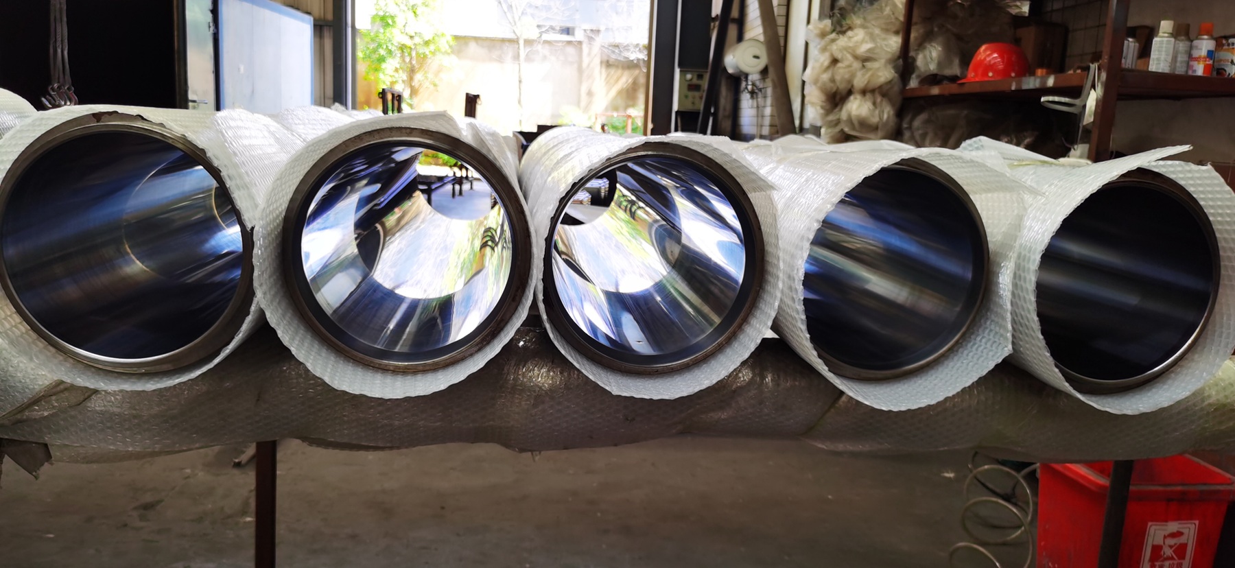
Concrete pump material cylinder alignment is the relationship between the axis of each hydraulic drive piston and the bore of the corresponding concrete-side cylinder. If those axes do not remain suitably aligned through the full stroke, the delivery piston can run with uneven contact, producing drag, localized polishing, seal distortion, or accelerated bore damage. Alignment cannot be diagnosed from one worn piston cup or one low-output complaint; bore geometry, piston condition, water-box evidence, mounting interfaces, and the pump manufacturer’s alignment check must be evaluated together.
What does material cylinder alignment mean?
A twin-cylinder concrete pump has a hydraulic drive cylinder and a concrete delivery, conveying, or material cylinder on each side. The drive rod moves the delivery piston through the material-cylinder bore. Alignment concerns the installed relationship among the drive cylinder, water box, material cylinder, valve housing or hopper, and pump-kit frame—not simply whether the replacement barrel is straight by itself.
That distinction prevents a common diagnostic mistake. A bore gauge can show whether a cylinder is oversized, tapered, or out of round, but it does not establish that the drive axis is correctly positioned relative to the installed bore. Conversely, an alignment tool may traverse without touching while the bore is already worn beyond the applicable service limit. Bore mapping and alignment verification answer different questions.
A Schwing service-training manual illustrates the principle with a model-specific alignment tool attached on the drive side. The tool is moved through the material cylinder at the lowest possible speed while clearance is observed. In that procedure, contact with the cylinder wall requires an immediate stop, and alignment is checked again after the valve housing and cylinder flanges are bolted together. The practical lesson is broader than that one design: the installed assembly must be verified through the stroke, and final bolt-up can change the result.
Why can misalignment damage a delivery piston or cylinder?
A delivery piston is designed to seal against the bore while reciprocating. It can accommodate the movement and small variations intended by its design, but it should not be used as the primary correction for a displaced cylinder axis. When the piston is forced consistently toward one side, its contact pressure is no longer distributed as intended. Friction and deformation can become concentrated at one clock position.
The possible result is a cause-and-effect chain: offset or angular error changes piston contact; the high-contact sector runs hotter or wears faster; the seal loses its intended shape; slurry or water may bypass; abrasive contamination then increases local wear. More than one mechanism can occur at the same time. A damaged bore, unsuitable piston, hardened concrete, poor lubrication, or incorrect assembly can create similar evidence, so the wear pattern is a clue rather than proof.
OEM operating instructions reinforce the need to inspect the piston-cylinder pair as a system. Schwing operating instructions state that leaking delivery pistons can cause premature pumping-cylinder wear and that continued sand ingress into the water box despite a new piston can indicate that the cylinders also require replacement. This does not make misalignment the automatic explanation; it shows why replacing a piston without investigating the bore and installed geometry can leave the root cause unresolved.
What observations justify an alignment check?
No single field symptom confirms misalignment. An alignment check becomes reasonable when several observations point toward directional loading or when the pump kit has been disturbed during overhaul.
| Observation | Possible alignment-related mechanism | What else must be ruled out |
|---|---|---|
| One piston cup wears more heavily at one clock position | The piston may be running with persistent side contact | Damaged bore, incorrect piston assembly, trapped debris, or hardened concrete |
| A narrow polished or scored track repeats along one side of the bore | A drive-axis error may be loading the same sector through the stroke | Foreign material, plating failure, corrosion, or previous piston damage |
| A new piston becomes hot, noisy, or difficult to move during controlled commissioning | Excessive side loading may be increasing drag | Wrong piston size, inadequate preparation, incompatible parts, or residual concrete |
| Alignment changes after the hopper or valve housing is tightened | Flange pull-up or frame/mounting distortion may be moving the cylinder | Dirt on mating faces, damaged pilots, incorrect seals, or unsupported components |
| One side repeatedly consumes pistons faster than the other | A side-specific geometry problem is possible | Different bore wear, lubrication, concrete ingress, hydraulic timing, or parts history |
Output loss by itself is weak alignment evidence. Low delivery can also result from poor cylinder filling, worn valve sealing surfaces, hydraulic leakage, short stroking, unsuitable concrete, or an undersized piston for the worn bore. The useful question is not “Does the pump have low output?” but “Is there repeatable directional evidence at the piston, bore, and mounting interfaces?”
When should alignment be verified?
Alignment is most efficiently checked when service work has changed an interface that locates the pump kit. Examples include replacement or removal of a material cylinder, drive cylinder, water box, hopper, valve housing, pump-kit frame component, or related mounting hardware. It is also relevant after impact damage, unexplained flange movement, structural repair, or repeated one-sided piston wear.
A new Concrete Pump Delivery Cylinder does not correct an alignment error elsewhere in the assembly. If the old cylinder failed with a distinct directional wear pattern, the shop should preserve that evidence before cleaning or discarding the parts. Record the cylinder side, clock position, stroke location, piston orientation, and condition of the opposite cylinder. Those records help distinguish a repeatable installed-geometry problem from uniform abrasive wear.
Alignment should also be rechecked at the assembly stage specified by the OEM. The Schwing training procedure checks the condition before and after the valve housing is secured. This matters because a cylinder that appears correctly positioned while loose may be pulled away from that position as pilots, O-rings, flanges, supports, and fasteners are brought together.
How should a workshop separate misalignment from bore wear?
Begin with evidence that does not depend on powered movement. After the machine has been isolated and made safe under the applicable manual, inspect the removed pistons, both bores, mating faces, pilots, mounting brackets, fasteners, and frame interfaces. Photograph clocked wear before polishing or cleaning changes its appearance.
Then map bore size at several axial stations and clock positions. Uniform enlargement points toward service wear rather than axis displacement. Taper or bell-mouth wear points toward a location-dependent mechanism. A repeated heavy sector can support an alignment hypothesis, but coating failure or debris may create a similar track. Surface condition and geometry must therefore be interpreted together.
Next, review assembly condition. Concrete, corrosion, burrs, damaged registers, compressed seals, bent brackets, or an unsupported hopper can prevent mating faces from seating as designed. Forcing flanges together with fasteners is not a valid substitute for identifying why they do not meet naturally. The correct fastener sequence, torque, allowable adjustment, and acceptance condition are model-specific.
Finally, perform the OEM alignment verification with the correct tool and competent personnel. Do not substitute a loose piston, improvised bar, or visual guess for a specified alignment tool. A tool also should not be allowed to scrape the bore merely to “find the tight side”; the referenced Schwing procedure explicitly calls for stopping if contact occurs.
Why a generic step-by-step adjustment is unsafe
Some alignment procedures require controlled powered movement while observations are made from defined safe positions. At other stages, personnel may need access near the water box or valve housing only after lockout, pressure release, and verification that stored energy is gone. Those two states must not be blurred.
The American Concrete Pumping Association warns that the hopper, concrete valve, agitator, and accumulator system can retain hazardous energy. Its back-end injury-prevention bulletin requires manufacturer procedures and confirmation that accumulator pressure is zero before hopper access. An ACPA safety manual also warns against removing water-box covers while the machine is stroking. For that reason, this article explains diagnostic logic but does not convert one manufacturer’s training procedure into universal instructions.
The machine-specific manual controls the tool, guards, operating mode, personnel positions, speed, isolation sequence, fastener torque, and acceptance limit. If those documents or the proper tool are unavailable, the prudent action is to stop and obtain OEM or qualified service guidance.
What should be recorded after alignment work?
A useful service record is more than “alignment OK.” It should make the result repeatable and help the next technician recognize a change.
- Machine make, model, serial number, pump-kit identification, and operating hours
- Left/right cylinder identification and orientation as viewed from a defined end
- Reason for the check, including the original wear pattern or replaced components
- Material-cylinder bore map and surface observations
- Delivery-piston part number, construction, measured condition, and installation orientation
- Condition of pilots, O-rings, flanges, brackets, supports, and mounting faces
- OEM procedure revision, alignment tool identification, and acceptance result
- Fastener specification and final torque record where the manufacturer requires it
- Result before final bolt-up and result after the connected housing or hopper was secured
- Controlled recommissioning observations, including abnormal noise, drag, leakage, or temperature
This record also improves replacement-parts purchasing. A cylinder inquiry should include more than nominal bore and length when the previous part showed abnormal directional wear. Provide flange and pilot geometry, mounting details, side/orientation, machine identification, photographs, and the bore/alignment findings. Marketplace listings commonly use “delivery cylinder,” “material cylinder,” and “conveying cylinder” for the same concrete-side barrel, but matching terminology does not prove that the interfaces or installed axis are correct.
Does minor off-center movement always require realignment?
No. The acceptable condition depends on the pump design and the specified test. In the referenced Schwing procedure, the alignment tool does not have to remain visually centered at every point; the important acceptance point described there is that it travels through the entire cylinder without touching. The manual also notes that the rubber ram accommodates minor misalignment in that design.
That statement should not be generalized into an arbitrary clearance or applied to another brand. It shows why technicians should use the OEM criterion instead of inventing a tighter or looser standard based on appearance alone.
Can alignment fix a worn material cylinder?
No. Alignment can correct an installed geometric relationship when the machine design provides an approved method, but it cannot restore bore diameter, roundness, surface finish, or coating integrity. A cylinder that is uniformly enlarged, deeply scored, flaking, corroded, or beyond its model-specific wear limit still needs an appropriate repair or replacement decision.
The inverse is also true: installing an unworn cylinder does not fix a displaced drive axis, damaged register, distorted frame, or poor assembly interface. Durable repairs address both the condition of the component and the geometry of the installed system.
Conclusion
Concrete pump material cylinder alignment should be investigated when wear is directional, piston damage repeats on one side, or major pump-kit interfaces have been disturbed. The diagnosis requires three separate checks: bore geometry and surface condition, evidence from the piston and water box, and an OEM-controlled alignment verification through the installed cylinder. Treating any one of those checks as a substitute for the others can result in new parts being installed into an unresolved fault.
Technical sources
- Schwing service training manual: material-cylinder alignment procedure and inspection principle
- Schwing service and parts brochure: material-cylinder alignment as a mechanic-level training subject
- American Concrete Pumping Association: Schwing intermediate service seminar topics
- American Concrete Pumping Association: prevention of hopper and back-end injuries
- Schwing S 47 SX III operating instructions: piston leakage and pumping-cylinder wear