Concrete Pump Parts Knowledge
Concrete Pump Reverse Pumping: What It Does, When It Helps, and Safety Limits
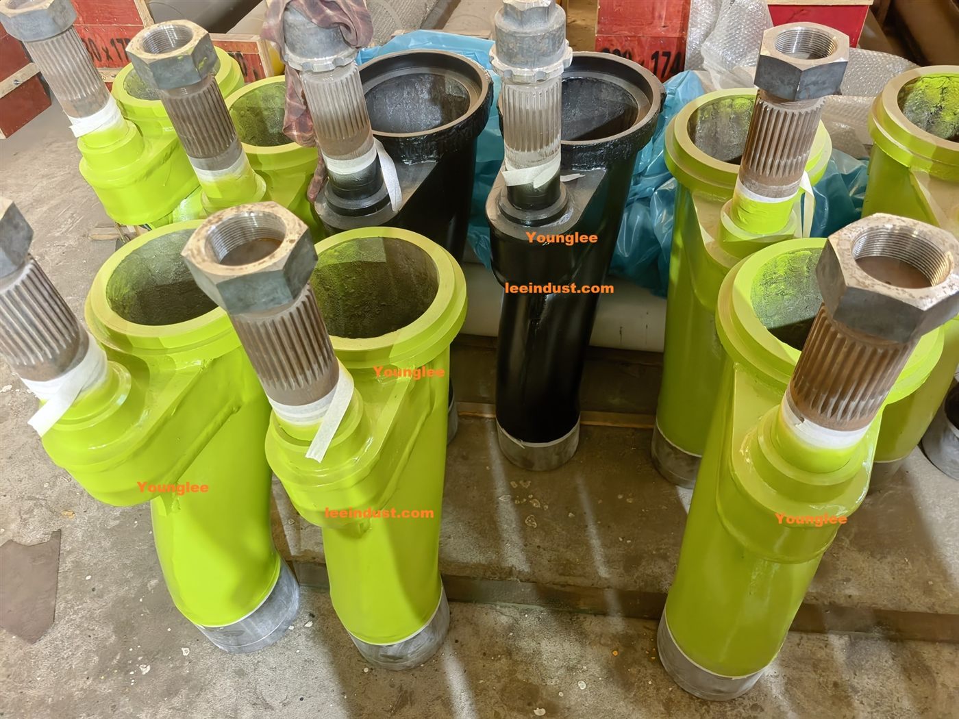
Concrete pump reverse pumping changes the material cycle so concrete is drawn back from the delivery side and returned toward the hopper instead of being pushed into the line. On many piston pumps, a trained operator may use the model-specific reverse function briefly to reduce delivery-line pressure or to rock a minor obstruction. It is not proof that every part of a blocked line is depressurized, and it is not a license to keep alternating forward and reverse until a hard plug moves.
The operating manual for the exact pump takes priority. Control logic, valve design, permissible cycling, pressure indication, boom or line layout, and isolation steps vary among machines. This article explains the engineering and diagnostic logic; it is not a blockage-clearing procedure.
What changes inside a concrete pump during reverse pumping?
In normal forward pumping, one material piston pushes a filled cylinder through the transfer valve and into the outlet while the other piston retracts and fills from the hopper. At the end of the stroke, the valve changes sides and the roles alternate. The drive-cylinder motion, concrete-piston motion, and transfer-valve position must remain synchronized.
REED’s S-tube operating explanation describes the reverse cycle directly: the piston on the suction stroke is connected through the S-tube to the delivery side rather than the hopper, while the opposite piston sends material back into the hopper. In practical terms, the machine is not merely turning a motor backward. Its controls change the relationship among the two material cylinders and the transfer valve so material moves toward the pump.
| Operating state | One material cylinder | Other material cylinder | Net material direction |
|---|---|---|---|
| Forward pumping | Pushes through the transfer valve to the outlet | Fills from the hopper | Hopper to delivery line |
| Reverse pumping on the REED S-tube arrangement described above | Draws from the S-tube or delivery side | Returns material to the hopper | Delivery side toward the hopper |
This explanation applies to the cited arrangement, not automatically to every pump. Other valve geometries, hydraulic circuits, electronic controls, and safety interlocks may execute or limit reverse mode differently. “Reverse pump,” “reverse pumping,” “pump reverse,” and “anti-pumping” are all encountered in operating and market language, but the control name does not establish an interchangeable procedure.
When can reverse pumping help?
Reverse pumping is principally useful when the OEM permits it as a controlled response to a developing blockage or retained delivery pressure. A short reverse movement can remove pump force from the concrete column and draw some material toward the hopper. Alternating directions may also rock a minor obstruction before it consolidates into a tighter plug.
That is a limited claim. The American Concrete Pumping Association blockage alert says to clear the discharge area, use forward-reverse action to rock a plug, and—if it does not release—reverse for several strokes to relieve line pressure before stopping. The alert also warns against jamming the obstruction or using compressed air. Putzmeister’s 2024 safety manual similarly instructs users not to push through a blockage by increasing pressure and describes reverse pumping followed by a forward restart, with line-pressure relief before a blocked section is removed.
The shared engineering logic is more important than copying a stroke count from one document: stop adding forward energy to an abnormal restriction, keep people out of the discharge and line-of-fire areas, and use only the applicable manufacturer’s method. A sequence written for one pump should not be transferred to another model.
Why does reverse pumping not prove the whole line is safe?
Reverse mode can reduce pressure at the pump end without demonstrating that pressure is zero everywhere. The ACPA’s hose-whipping guidance explicitly cautions that some pressure may remain after reversal. This matters because a blocked delivery system is not necessarily one continuous, freely communicating volume.
A plug can isolate material farther down the line. Two restrictions can trap a pressurized section between them. Air introduced during a low-hopper event, line change, restart, or unsuccessful blockage response can store considerably more energy than an incompressible concrete column. A vertical or otherwise constrained layout may also retain load after active pump force is removed. The exact condition depends on the machine, line arrangement, material, and obstruction.
The pump gauge adds another source of false confidence. On many machines it reports hydraulic-circuit pressure, not a direct measurement at every delivery-pipe segment. A falling or apparently low gauge reading shows what the monitored circuit is doing; it does not verify that an isolated hose, reducer, elbow, riser, or section behind a plug has no stored pressure. Stopping the engine proves even less.
For that reason, never loosen a coupling, strike or drill a blocked line, reach into the hopper, or approach an end hose merely because reverse mode was selected or a gauge changed. Putzmeister’s manual states that delivery lines must not be opened while pressurized and that the concrete column must be depressurized by reverse pumping before opening. The complete OEM shutdown, isolation, verification, and line-opening procedure still applies, along with site exclusion controls and trained personnel.
What can the pump’s response to reverse mode tell you?
Reverse response is useful diagnostic evidence, but it is not a one-observation diagnosis. A technician should combine the control command, piston and valve motion, material return, pressure trend, line behavior, and the events preceding the stoppage.
| Observation | What it may indicate | What still needs verification |
|---|---|---|
| Pressure rises quickly in forward mode and some material returns to the hopper in reverse | A restriction exists and the pump-side material path remains at least partly connected | Blockage location, concrete condition, reducer or hose condition, and whether pressure remains elsewhere |
| The control shows reverse, but piston or valve motion is incomplete or irregular | A control, hydraulic, sensor, switching, or mechanical problem may be present | Model-specific fault codes, hydraulic tests, valve travel, and stored-energy isolation before inspection |
| One side behaves differently from the other | Unequal cylinder filling, piston sealing, valve alignment, or flow-path restriction is possible | Compare both material cylinders, piston cups, transfer-valve contact, and operating history |
| Reverse-forward action temporarily restores flow but the restriction returns | The root cause may still be present: unsuitable concrete, lost lubrication layer, hardened buildup, leaking joints, worn valve parts, or poor line geometry | Mix and batch changes, delay time, line route, priming, wear, leakage, and cleaning condition |
| The hydraulic gauge falls but a hose or pipe section remains rigid or loaded | The monitored pump circuit may be unloaded while material pressure is trapped elsewhere | Follow the OEM pressure-release and verification method; do not use touch or coupling movement as a test |
The table is deliberately framed as observation, possible mechanism, and verification. For example, incomplete reverse motion does not automatically condemn the valve assembly. A proximity sensor, directional valve, hydraulic supply, accumulator circuit, control interlock, or mechanical obstruction can disrupt the same sequence. Parts should be ordered only after the failed function has been identified.
When should repeated reversing stop?
Repeated reversing should stop when the applicable manual’s attempt limit or response condition is reached, when the obstruction does not move, when pressure or machine behavior remains abnormal, or when any unsafe condition develops. More cycles are not neutral. Continuing to work a plug can squeeze paste and water through the restriction, consolidate coarse aggregate, introduce air, heat the hydraulic system, or expose delivery and valve components to repeated loading.
A blockage is especially unlikely to be solved by control input alone when material has begun to set, a foreign object is trapped, a hose liner has failed, a reducer is mechanically obstructed, or hardened buildup has reduced the passage. The safe next action is an equipment- and site-specific decision made under the manufacturer’s instructions—not an improvised increase in pressure.
Compressed air is not a substitute. Both ACPA and Putzmeister warnings reject using it to force through a blockage. Compressed gas can store energy and create a violent discharge, line movement, or hose whip when the plug releases.
How should a pump be restarted after successful reversal?
A temporary return of material to the hopper does not establish that the line is clear or that the original cause is gone. Before restarting, the trained operator should confirm the machine state and follow the exact restart instructions for the pump and delivery system. Personnel must remain clear of the discharge and end-hose movement area.
The ACPA hose-whipping safety bulletin advises keeping people away while the operator slowly tests forward flow and allowing them to return only after concrete flows steadily. That distinction matters: the first forward movement after reversal is a verification phase, not normal production. Air, a mobile plug, or an incompletely filled section can make discharge behavior unpredictable.
Once flow stabilizes, compare pressure behavior, stroke rhythm, valve switching, hopper return, and output with the condition before the event. If the pump immediately returns to high pressure, rough changeover, leakage, or uneven filling, stop and diagnose rather than treating another reversal as routine operation.
When does a reverse-pumping problem point to replacement parts?
Reverse pumping depends on the same synchronized components used in forward operation. In an S-tube system, the Concrete Pump S-Valve Assembly must connect the intended material cylinder to the correct side of the flow path. Its swing mechanism, shaft and bearings, wear plate and cutting ring, hydraulic controls, and sealing contact all influence whether the changeover is complete. Other valve designs have different interfaces and must be assessed against their own documentation.
The Concrete Pump Delivery Cylinders and piston cups also matter. Excessive bore or piston-seal wear can permit bypass, reduce filling, and make left/right behavior unequal. Those symptoms may become more visible during a reverse test, but the test does not identify the failed part by itself.
Before requesting a quotation, record the pump manufacturer, exact model and serial number, pump-kit or valve configuration, displayed fault codes, which controls were selected, left/right piston and valve response, pressure trend, whether material returned to the hopper, and the events immediately before the blockage. Add photographs only after the machine has been safely isolated and cleaned under the approved procedure. This information helps a repair shop distinguish a control problem from a worn flow component and reduces the risk of ordering a visually similar but incompatible valve or cylinder part.
Conclusion
Concrete pump reverse pumping changes the synchronized cylinder-and-valve cycle so material moves from the delivery side back toward the hopper. Used within the correct OEM procedure, it can reduce pump-side delivery pressure and may release a minor obstruction. It cannot certify that every line section is depressurized, cure an unsuitable mix or hardened blockage, or replace diagnosis of repeated high-pressure events.
The professional decision sequence is simple in principle: recognize the abnormal condition, stop adding forward pressure, clear people from the hazard area, apply only the manufacturer-approved reverse response, and treat the result as evidence rather than proof. If stable forward flow does not return under the prescribed conditions, isolate the system and investigate the concrete, line, transfer valve, cylinders, controls, and hydraulic switching circuit.
Technical references
- REED Concrete Pumps: How a Concrete Pump Works
- REED B20HPC PLC Operation and Maintenance Manual
- American Concrete Pumping Association: Safety Steps to Remove a Blockage
- American Concrete Pumping Association: Hose Whipping Safety Bulletin
- Putzmeister Safety Manual for Concrete Delivery and Placing Machines, Rev. 20