Concrete Pump Parts Knowledge
Concrete Pump S-Valve Outlet Seals: Leak Paths, Binding, and Ordering Checks
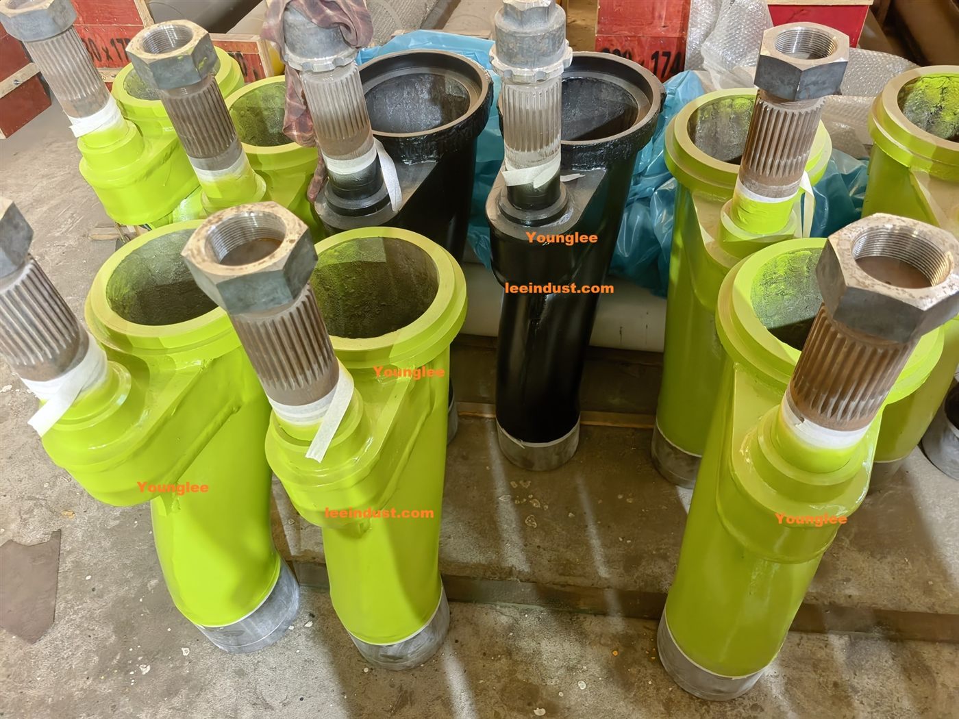
A concrete pump S-valve outlet seal keeps abrasive contamination away from the outlet-end support while retaining lubricant around the rotating or oscillating valve interface. It is not the same seal as the wear ring against the spectacle plate. When the outlet stack loses lubrication, is assembled in the wrong orientation, runs on a damaged sleeve, or is forced out of alignment, the valve can become harder to shift and the repair can fail again even after new seals are installed.
Which seal is the “S-valve outlet seal”?
On an S-tube or swing-tube concrete pump, the curved valve has two very different sealing duties. At the inlet end, a wear ring or cutting ring meets the stationary wear plate around the material-cylinder openings. That face contact limits concrete and pressure loss back into the hopper. At the discharge end, the valve passes through a support, bearing sleeve, discharge plate, nipple, pressure connection, or seal housing before joining the delivery outlet. Seals at this supported outlet interface help exclude slurry and retain grease.
Parts books and workshops do not use one controlled name for the outlet components. Depending on the pump, an inquiry may mention an outlet seal, big-end seal kit, discharge-nipple seal, transfer-tube bearing gasket set, pressure-flange seal, YX ring, J seal, shaft seal, O-ring, or bearing-housing seal. Some names describe one elastomer; others describe a kit containing several seals, backup or retaining rings, bearing elements, and O-rings.
This naming ambiguity is commercially important. A photograph of a loose black ring cannot establish its location, profile, material, orientation, or pump compatibility. The outlet seal must be identified as part of a model-specific assembly.
How is an outlet seal different from the wear-ring seal?
| Interface | Primary job | Typical evidence when the interface is deteriorating |
|---|---|---|
| Wear ring against wear plate | Seals the selected material cylinder to the valve inlet during a delivery stroke | Paste return into the hopper, reduced output, grooves, chipped hardfacing, or uneven contact |
| Outlet bearing and seal stack | Supports and seals the valve where it passes through the hopper outlet or discharge support | Contaminated grease, abnormal purge, binding, seal damage, journal or sleeve wear, or concrete tracking toward the support |
| Delivery-pipe coupling gasket | Seals a static, clamped pipeline joint downstream of the pump outlet | External leakage at a coupling, damaged gasket seat, loose or unsuitable coupling hardware |
The symptoms can interact. If the outlet support binds, the valve may not reach its commanded position cleanly, which can disturb wear-ring contact. Conversely, concrete escaping elsewhere in the hopper can obscure the original leak path. Diagnosis should therefore begin by cleaning and marking the interfaces, then observing where fresh contamination or lubricant reappears under the manufacturer’s approved test.
Why can a new outlet seal leak or bind?
A new seal can fail immediately when the surrounding geometry or assembly condition remains defective. The following causes deserve separate verification.
Incorrect seal orientation or stack order
Lipped and profiled seals are directional. Their pressure-facing side, open side, backup ring, spacer, and O-ring positions must match the assembly drawing. The REED B20 manual instructs technicians to replace outlet seals in the proper orientation, apply grease, and install the outlet seal housing. That wording matters: a ring that fits into the groove is not necessarily installed correctly.
Dry running or a blocked grease path
The seal lips and adjacent bearing surfaces depend on the lubrication arrangement designed for the machine. REED’s procedure calls for greasing the S-tube fittings until grease emerges from the seals after assembly. This is model-specific commissioning evidence, not permission to force unlimited grease into every pump. If grease appears at the fitting but not at the intended purge point, the line, drilling, groove, or distributor may be restricted.
A worn sleeve, journal, bearing, or housing
A seal cannot restore the running surface it contacts. Scoring, corrosion, a wear step, coating loss, taper, or excessive clearance can damage a new lip or create a leakage path. If the supporting bearing or sleeve allows the valve end to move off-center, the seal load becomes uneven. Replacing the elastomers alone may briefly hide the symptom while the same hard-part defect continues.
Outlet misalignment
The Mayco LS300 operation manual links a slow shuttle-cylinder stroke to an improperly lubricated discharge-nipple seal or a misaligned hopper creating excessive friction at the outlet nipple bearing sleeve. This is a useful diagnostic relationship: slow valve movement does not prove a hydraulic-cylinder fault. Mechanical drag at the outlet support can consume the available shifting force.
Hardened concrete or an incorrect installation surface
Concrete residue behind a housing, on a pilot, or beside a seal can prevent concentric assembly. Burrs and sharp edges can cut a lip during installation. A sealant bead placed where the manual does not specify it can block a lubricant path or prevent the housing from seating. Cleanliness is therefore dimensional control, not just appearance.
What do grease and slurry at the outlet actually prove?
Neither observation proves one failed part by itself. Fresh grease emerging from a designed purge area immediately after correct lubrication may be normal. Grease carrying grit, cement fines, rust, or water suggests that the exclusion boundary deserves inspection, but the contamination source and flow direction still need to be established.
Concrete paste outside the intended flow path is more serious, yet its origin can be misread. Material may track from the wear-ring area, a housing joint, a damaged outlet component, or residue left during washout. Before dismantling, photograph the clean, dry assembly; mark orientation; note which side becomes wet first; and record whether the symptom appears during valve shifting, during the delivery stroke, or only during cleaning.
| Observation | Possible mechanism | Verification before ordering |
|---|---|---|
| Valve shifts slowly in both directions | Outlet-seal drag, dry bearing sleeve, hydraulic supply problem, or binding elsewhere | Lubrication path, outlet concentricity, unloaded mechanical movement, hydraulic command, and OEM pressure test |
| Fresh seal lip is cut after installation | Sharp edge, damaged sleeve, wrong tool, tilted housing, or incorrect seal profile | Journal and lead-in condition, installation method, profile, orientation, and housing alignment |
| Contaminated grease appears repeatedly | Exclusion seal failure, worn running surface, excessive clearance, or washout entry | Seal path, sleeve and bearing condition, purge route, washout practice, and grease specification |
| Outlet housing becomes hot or valve load rises | Insufficient lubrication, excessive preload, interference, or misalignment | Stop the test; confirm assembly dimensions, free movement, lubricant delivery, and model-specific adjustment |
| Leak returns soon after a complete seal kit | Hard-part wear, housing damage, wrong kit, reversed seal, or unresolved misalignment | Part numbers, serial range, journal dimensions, housing bore, stack order, and installed axis |
How should the outlet support be inspected?
First place the machine in the safe condition specified by its manufacturer. Hopper work can expose technicians to the agitator, S-valve, hydraulic actuators, accumulator energy, heavy suspended parts, and residual concrete pressure. The ACPA Safety Procedures for Concrete Pump Mechanics requires lockout/tagout and control of stored energy; a stopped engine alone is not proof that the mechanism cannot move.
Preserve evidence before washing everything clean. Photograph grease tracks, paste paths, displaced rings, witness marks, and the relationship between the outlet, housing, and hopper. Record whether the machine was recently rebuilt, whether the problem followed a blockage or washout, and whether shifting became progressively slower or changed suddenly.
During controlled disassembly, support the valve with the lifting method and tooling required by the manual. Do not let its mass hang on a seal or bearing edge. Identify and lay out every ring in removal order, with its open side and orientation marked. Compare the removed stack with the parts drawing instead of assuming the previous installation was correct.
Inspect the complete running system:
- seal lips, O-rings, backup rings, retainers, spacers, and grooves;
- outlet journal, chromed sleeve, bearing sleeve, or discharge nipple for scoring, wear steps, corrosion, and coating loss;
- bearing or bushing for clearance, cracking, embedded grit, or asymmetric contact;
- housing bore, pilots, flanges, fasteners, and seating faces for fretting, burrs, distortion, or concrete residue;
- grease fittings, hoses, internal drillings, grooves, and intended purge points; and
- hopper and valve alignment, including whether the valve rotates around the intended outlet centerline.
The Mayco ST45HRM parts manual illustrates why the entire stack matters: it lists a discharge sleeve, discharge-plate bearing, seal, discharge nipple, O-rings, grease fittings, and separate swing-axle sealing parts. Another model may group or name them differently. The drawing for the exact serial configuration remains controlling.
What information should an outlet-seal RFQ include?
Do not order from diameter alone. A useful request for quotation should include:
- pump manufacturer, exact model, serial number, production period, and pump-kit or hopper version;
- verified part number for the seal, kit, housing, bearing, sleeve, or complete outlet assembly, including suffixes;
- an overview photograph showing whether the part is at the valve inlet, outlet, shaft, or delivery-line coupling;
- assembly drawing position and the quantity used at that exact location;
- old stack photographed in removal order, with lip direction and installed orientation marked;
- groove diameter and width, shaft or sleeve diameter, housing bore, and axial stack length measured only with suitable tools;
- running-surface condition and measured wear, not merely the nominal new-part diameter;
- related bearing, bushing, sleeve, O-ring, retainer, spacer, grease fitting, and housing scope; and
- the observed failure: leakage path, contamination, binding, temperature rise, abnormal clearance, or early repeat failure.
Do not infer elastomer type, hardness, pressure rating, or chemical compatibility from color. Do not substitute a generic seal simply because its inside and outside diameters appear close. Profile geometry, lip direction, cross-section, material, running clearance, and the adjacent hard parts determine whether it can work in the assembly.
When the outlet support or valve body is no longer serviceable, compare the risk and labor of a partial repair with a correctly matched Concrete Pump S-Valve Assembly. The buying decision should be based on inspected interfaces and verified scope, not on the assumption that a larger parts package automatically solves the root cause.
Can extra grease compensate for a worn outlet seal?
No. Grease can confirm that a path is open and provide the intended lubricant film, but it cannot rebuild a grooved sleeve, center a misaligned valve, restore a damaged housing bore, or correct a reversed seal. Repeatedly adding grease while abrasive contamination continues to enter may only carry more contaminated lubricant through the support.
Should the seal, bearing, and sleeve be replaced together?
Not by a universal rule. Replace the parts that fail the model-specific inspection and service criteria, while considering how one damaged surface affects the others. A seal installed on a worn sleeve is unlikely to last; a new bearing in an enlarged housing may not control the valve axis; and a sound sleeve does not need replacement merely because a disposable seal reached normal wear. Record measurements and follow the OEM repair scope.
Conclusion
An S-valve outlet seal is part of a supported, lubricated, and aligned discharge-end assembly. It should not be confused with the wear-ring face seal or the downstream pipe-coupling gasket. When leakage, contaminated grease, heat, or slow shifting appears, inspect the seal orientation, lubricant path, running surface, bearing clearance, housing, and outlet alignment as one system. A precise RFQ then connects the correct machine and drawing to the complete local stack, preventing a seal-only repair from being repeated against the same damaged geometry.
Technical sources
- REED B20 operation and maintenance manual: outlet-seal orientation, greasing, housing installation, and S-tube adjustment sequence.
- Mayco LS300 operation manual: discharge-nipple lubrication, outlet-bearing friction, hopper alignment, and slow shifting.
- Mayco ST45HRM parts manual: model-specific outlet sleeve, bearing, seal, nipple, O-rings, and lubrication components.
- ACPA Safety Procedures for Concrete Pump Mechanics: lockout/tagout, stored-energy control, and hopper-area hazards.