Concrete Pump Parts Knowledge
Concrete Pump S-Valve Wall Thickness: How to Measure Wear and Decide Replacement
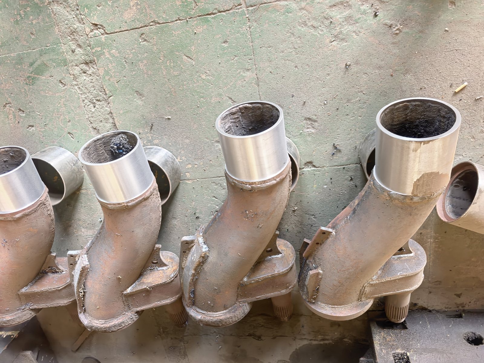
A concrete pump S-valve should not be judged by appearance alone. The useful inspection result is a mapped set of remaining-wall readings, interpreted against the exact pump model, the maximum possible concrete pressure, the tube construction, and the OEM limit. The lowest valid reading—not an average—usually controls the decision. Cracks, deformation, damaged shaft attachments, or an unreliable ultrasonic signal can require removal even when most readings look acceptable.
This matters because the S-valve, also called an S-tube or S-transfer tube, is both a concrete passage and a dynamically loaded switching member. Abrasive material wears its bore while the tube repeatedly accelerates, stops, and transmits switching torque. A single spot check at an easy-to-reach location can miss the condition that actually limits continued service.
Why S-Valve Wall Thickness Is a Separate Inspection Question
Wear at the cutting ring and wear plate affects the sealing interface. S-valve wall loss affects the pressure-containing body of the transfer tube. The two conditions can occur together, but adjusting the cutting ring does not restore metal removed from the tube wall.
That distinction prevents a common diagnostic mistake. Material returning to the hopper, reduced output, or visible grout leakage may direct attention to the valve faces. Those symptoms do not establish that the tube wall is sound. Conversely, a tube can become locally thin without producing an obvious change in pumping output.
The maintenance plan should therefore treat contact-face inspection and wall-thickness inspection as related but separate tasks. When the assembly is opened, it is practical to inspect the cutting ring, wear plate, wear sleeve, bearings, seals, shaft connection, and tube body together. LeeIndust’s Concrete Pump S-Valve Assembly page shows the product family and the interfaces that buyers commonly need to identify when planning replacement.
There Is No Universal Minimum S-Valve Thickness
Minimum acceptable wall thickness is an OEM- and model-specific engineering limit. It depends on geometry, material, tube construction, maximum possible pressure, the highly loaded shaft-to-tube region, and the manufacturer’s design assumptions. A thickness taken from another pump should not be transferred to the machine under inspection.
Published OEM examples demonstrate the variation. A Putzmeister P 715 manual gives an approximate 3 mm guide value for its S-transfer tube at a maximum possible operating pressure of 70 bar. The same manual warns that variable dynamic loading means the tube can still fail at a pressure assumed to be permissible. An Alliance service bulletin for its pumps gives different thickness/maximum-pressure pairings and calls for several measuring points, including the area where the shaft connects to the valve. These documents are evidence that pressure and design context matter; they are not a cross-brand lookup table.
| Published example | What the source states | How it should be used |
|---|---|---|
| Putzmeister P 715 manual | Approximately 3 mm at 70 bar maximum possible operating pressure; measure particularly at stress points | Only for the stated machine and manual revision; confirm the serial-number-specific document |
| Alliance service bulletin TSB-24.20-2019-001 | Check after 800 pumping hours; examples pair 5, 6, and 8 mm with 130, 148, and 224 bar respectively | Alliance guidance for the pumps covered by that bulletin, not a universal industry schedule |
| Any replacement decision | Use maximum possible pressure and the lowest reliable local reading | Obtain the applicable OEM limit when the model, tube design, or pressure configuration differs |
Pressure configuration deserves special attention. A machine may normally be operated below its rated capability, but a blockage or control setting can expose the system to a higher pressure. The Putzmeister manual specifically connects the minimum wall-thickness decision to maximum possible operating pressure, not merely the gauge value observed on a typical pour.
Where Should the S-Valve Be Measured?
A defensible inspection covers the tube as a surface, not as one point. Start with the OEM diagram if it identifies high-load or high-wear zones. Then create a repeatable grid that covers the bend, inlet and outlet transitions, and the shaft-to-tube load-transfer region. Mark axial stations along the tube and take multiple readings around the circumference at each station.
Three mechanisms explain why a grid is necessary:
- Abrasive flow is not uniform. Aggregate-rich concrete changes direction through the transfer tube, so local particle trajectories and velocity distribution can create asymmetric internal wear.
- Switching load is not uniform. The shaft connection transfers torque into the tube body. Putzmeister and Alliance both call attention to this region, independently of flow wear.
- Repairs and construction details affect the signal. Hardfacing, liners, welds, coatings, and tight curvature may require a different ultrasonic setup or an alternative verification method.
A practical map might label stations from the inlet face to the outlet and clock positions around each section. The exact number and spacing of readings should be defined by the OEM procedure, component geometry, previous wear pattern, and the inspection specialist. The goal is to find the local minimum and make the next inspection comparable—not to generate a large collection of untraceable numbers.
How to Obtain Reliable Ultrasonic Thickness Readings
Ultrasonic thickness testing measures the travel time of sound pulses through a material. ISO 16809:2025 describes principles for contact and immersion ultrasonic thickness determination, while ASTM E797/E797M covers manual pulse-echo contact measurement from one side. Neither standard supplies a concrete-pump discard thickness. They govern measurement principles; the acceptance limit must come from the applicable pump or component documentation.
1. Identify the tube construction before setting the gauge
Confirm whether the sound path is homogeneous base metal or includes a bonded liner, deposited hardfacing, repair layer, or other multi-layer construction. Material sound velocity and interface echoes affect the result. A procedure validated on a plain carbon-steel pipe should not be assumed to read a layered S-tube correctly.
2. Prepare a measurement surface, not a cosmetic surface
Remove concrete residue, loose corrosion, thick paint, and scale at each test spot without grinding away structural metal. The probe must sit stably, and couplant must transmit sound between probe and part. If curved geometry prevents consistent contact, use an appropriate small-footprint or delay-line transducer and a procedure qualified for the radius.
3. Calibrate for the material and expected range
Use a traceable reference of known thickness and similar acoustic properties where the inspection procedure requires it. Confirm calibration before the survey and recheck it afterward. If the closing check has drifted, the affected readings should not be accepted without investigation.
4. Record the waveform quality as well as the displayed number
A stable digital value is not automatically a valid wall reading. Rough internal wear, poor coupling, laminations, geometry echoes, and multiple material layers can produce false or ambiguous indications. Suspect minima should be repeated from nearby positions and, when possible, confirmed using another orientation or method by qualified personnel.
5. Preserve the minimum and the map
Do not average a thin spot into several thicker readings. Record the lowest validated reading, its precise location, the instrument and probe, calibration reference, surface condition, date, pump hours or pumped volume where available, tube identification, pressure configuration, and inspector. This turns the survey into trendable condition data.
What Does a Thickness Map Actually Tell You?
| Observation | Possible interpretation | Verification or action |
|---|---|---|
| One isolated low reading with unstable coupling | Surface or geometry error; local pit; true thin spot | Clean, recalibrate, repeat around the location, and review the ultrasonic response |
| Consistent thinning through one side of the bend | Directional abrasive wear | Extend the grid along and around the bend; compare with previous maps |
| Thinning or damage near the switching-shaft connection | Combined wear and load concern in a stressed region | Apply the OEM-specific inspection and replacement rule; inspect for cracking or distortion |
| Wall readings above limit but a crack is present | Thickness alone does not establish fitness for service | Remove from service and obtain the OEM-approved repair or replacement disposition |
| Most readings unchanged but a small zone is trending down | Localized wear is controlling life | Shorten the inspection interval based on trend and operating conditions |
| No credible back-wall echo through a lined or hardfaced zone | The selected technique may not measure the intended layer | Do not invent a thickness; validate another probe, calibration, or inspection method |
The map supports two different decisions. The first is immediate fitness for service: does any defect or minimum reading cross the applicable removal criterion? The second is planning: how quickly is the controlling zone changing, and is another full service interval realistic? Trend calculations are useful only when locations and technique are repeatable.
Operating history gives context but does not replace measurement. Pumped volume, hours, concrete mix, aggregate hardness and shape, pressure, blockage history, cleaning practice, and prior repairs can influence wear. A volume-based change interval alone cannot prove remaining wall thickness.
Can a Worn S-Valve Be Repaired by Hardfacing or Welding?
Do not treat field welding as an automatic way to recover a rejected transfer tube. Adding wear material to the bore may change local abrasion resistance, but it does not automatically restore the original load path, base-metal section, geometry, weld integrity, shaft alignment, or pressure capability. Heat input can also affect adjacent material and dimensional relationships.
A repair is defensible only when the pump or component manufacturer accepts the repair scope and a qualified facility has controlled the material, weld procedure, preheat and post-weld requirements, machining, balance or alignment where applicable, and final examination. If those inputs are unavailable, replacement is the safer and more traceable disposition. Cosmetic filling of a thin zone should never be used to hide an unverified pressure-boundary condition.
What Should Be Supplied When Ordering a Replacement S-Valve?
A model name alone is often insufficient, especially when a pump family has multiple pressure versions or design revisions. Send the supplier a structured identification package:
- pump manufacturer, exact model, serial number, year, and parts-book revision;
- OEM part number and any markings on the removed S-valve;
- low- and high-pressure configuration and maximum possible concrete pressure;
- inlet and outlet diameters, center distances, overall envelope, and mounting-face details;
- shaft diameter, spline or key specification, lever orientation, and bearing or wear-sleeve interfaces;
- wear plate and cutting-ring part numbers and their measured condition;
- liner, hardfacing, or other internal wear construction if specified;
- clear photographs of the complete tube, shaft area, inlet face, outlet, and identification marks;
- the wall-thickness map and the reason for removal.
Keep original drawing units and precision. Converting dimensions prematurely or rounding identifying measurements can create an apparent match that does not fit. The quotation should state which dimensions, material condition, interfaces, inspection documents, and included wear parts have been confirmed.
A Practical Replacement Decision
Replace or formally remove the S-valve from service when the lowest validated reading reaches the model-specific OEM limit, when a crack or structural defect is found, when the tube cannot be measured reliably enough to demonstrate compliance, or when an approved repair disposition cannot be established. Do not extend service merely because the average thickness is comfortable or because the pump usually operates at low pressure.
If the tube remains above its limit, use the measured trend to set the next inspection before the projected minimum could be reached, allowing for uncertain operating conditions and localized wear. Keep the map with the machine record so the next survey returns to the same controlling zones.
Conclusion
Concrete pump S-valve wall-thickness inspection is a condition-mapping task, not a single-number check. Identify the exact tube construction, use a validated ultrasonic method, measure the bend and shaft-load region systematically, retain the lowest credible reading, and compare it with the correct OEM pressure-specific limit. That process separates seal-face maintenance from pressure-boundary wear and gives maintenance teams a traceable basis for continued service, planned replacement, or engineering review.
Technical References
- Putzmeister P 715 operating instructions, section 8.4.15.3, “Measuring the wall thickness of the S transfer tube.”
- Alliance Concrete Pumps service bulletin TSB-24.20-2019-001, “Guidelines for changing S-Valve tube in our pumps.”
- ISO 16809:2025, Non-destructive testing—Ultrasonic thickness determination.
- ASTM E797/E797M, Standard Practice for Measuring Thickness by Manual Ultrasonic Pulse-Echo Contact Method.