Concrete Pump Parts Knowledge
Concrete Pump Wear-Plate O-Rings: Leak Diagnosis and Ordering Checks
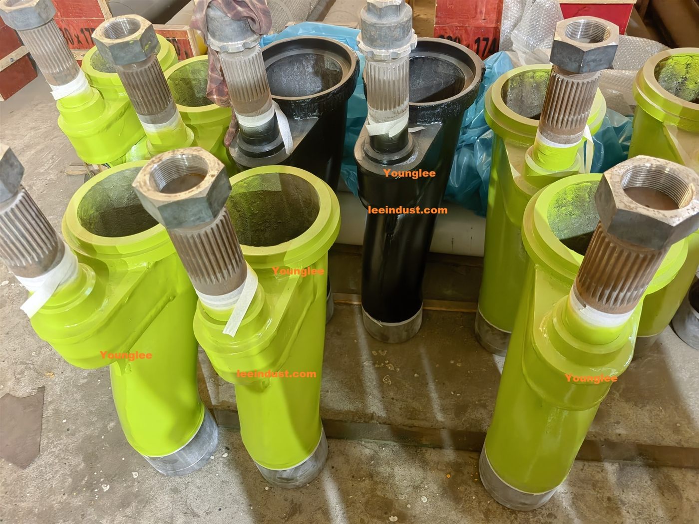
A concrete pump wear-plate O-ring seals the stationary interface between a material cylinder and the back of the wear plate or its adapter. It does a different job from the cutting ring: the cutting ring seals against the working face of the wear plate while the valve switches, whereas the cylinder O-ring prevents cement paste and slurry from finding a path behind the plate. A leak at one interface can resemble a leak at the other, so replacing the visible wear parts without inspecting the hidden seals can leave the original fault in place.
This distinction matters during a hopper overhaul. Current OEM documents show that the number, size, name, and surrounding parts vary by pump model. The correct repair therefore starts with the exact assembly drawing, not with a generic O-ring selected by apparent diameter.
Which seal is the “wear-plate O-ring”?
Names are inconsistent. A parts book may call it a wear-plate O-ring, cylinder O-ring, concrete-cylinder O-ring, or simply identify an O-ring by its dash number or dimensions. The location is more reliable than the name: it surrounds the circular passage where each Concrete Pump Delivery Cylinder meets the stationary plate or cylinder adapter at the hopper end.
Do not confuse it with the rubber energizer behind the cutting ring, an O-ring on the S-tube shaft, a piston-adapter O-ring, or the seal between a delivery cylinder and the water/lubrication box. These parts can be close on an exploded drawing but seal different interfaces.
The model differences are not minor. The Mayco LS600P parts manual lists two wear-plate O-rings separately from two oiler-plate O-rings. The REED B20 manual shows two main O-rings plus two O-rings associated with anti-chip rings and concrete-cylinder adapters. A REED B50HPSC drawing uses another arrangement and part number. Those examples establish a purchasing rule: “two cylinder seals” is not a complete specification.
How does this hidden static seal work?
The wear plate is clamped against the cylinder ends or adapters. When correctly sized and seated, the O-ring is compressed in its groove and closes the leakage path around the cylinder opening. Unlike the piston cup or the cutting ring, it is not intended to slide continuously during pumping. Its challenge is static sealing in an assembly exposed to abrasive cement paste, pressure cycling, washout water, hardened residue, and repeated disassembly.
The metal geometry controls the seal. The groove, cylinder end, adapter, plate back, locating rings, fasteners, and support surfaces must place the O-ring under the intended compression. A new seal cannot compensate reliably for a damaged groove, a plate that will not seat flat, corrosion, trapped aggregate, an incorrect adapter, or a cylinder end that is no longer positioned correctly.
General seal engineering supports this logic. The Parker O-Ring Handbook identifies pinching, twisting, dirt, metal particles, sharp edges, wrong size, and inappropriate lubrication as common installation-damage causes. In a concrete pump, the risk is intensified by abrasive residue around the hopper and wear-plate area. The handbook is useful for failure analysis, but the pump manufacturer’s drawing still controls the actual size, compound, groove, sealant, and assembly procedure.
What symptoms can a cylinder-to-plate leak produce?
A failed wear-plate O-ring can permit paste or wash water to migrate behind the plate, leave a wet or cement-stained track around a cylinder opening, contaminate a joint, or contribute to internal recirculation. It may also allow residue to pack into a space that should remain clean and fully seated. None of these observations proves the O-ring is the only failed part.
| Observation | Possible mechanism | What separates it from other faults |
|---|---|---|
| Paste or damp residue appears behind the wear plate near one cylinder opening | Damaged, omitted, pinched, compressed, or incorrectly sized cylinder O-ring; damaged groove or seating face | Remove and inspect the back-side leak track, seal, groove, cylinder end, and plate support surface |
| Concrete surges or sprays back into the hopper during a stroke | More commonly a loss of cutting-ring-to-wear-plate face contact, although multiple leaks can coexist | Observe where material crosses the working face; inspect cutting ring, energizer, wear plate, valve travel, and back-side seals separately |
| A new O-ring leaks immediately after overhaul | Installation damage, wrong part, debris, wrong stack, uneven seating, or an unresolved metal defect | Do not assume a defective batch; compare the assembly with the serial-specific drawing and read the physical damage pattern |
| One side repeatedly leaks while the other remains dry | Local groove, adapter, cylinder-position, clamping, or surface-condition problem | Compare the two sides without swapping unidentified parts; record where the leak track begins and ends |
| Output falls with no visible back-side leak | Face-seal wear, poor valve travel, piston/cylinder bypass, incomplete filling, short stroke, or hydraulic trouble | Diagnose the full pumping cycle; output loss alone does not identify a static O-ring |
Why the “volcano effect” does not automatically identify the O-ring
Multiquip’s LS300 operating guidance describes sudden hopper-level changes, slurry squirting into the air, lower delivery pressure, and frequent material packs as signs that the cutting ring and wear plate are no longer seating correctly. That is leakage across the moving face interface. The cylinder O-rings sit behind the wear plate and seal the stationary cylinder openings.
The two seal systems meet at the same general area, which is why visual diagnosis can be misleading. A deeply worn plate, weak or damaged energizer, incomplete S-tube travel, or loose mechanical support can create front-face leakage even when both cylinder O-rings remain intact. Conversely, a clean-looking cutting-ring track does not prove that the back-side seals are sound.
When a Concrete Pump S-Valve Assembly is opened for service, divide the evidence into two maps: the circular contact track on the working face, and any paste, staining, washout path, or packed residue on the back side. This simple separation prevents one symptom from being assigned to the wrong interface.
Inspection should follow the leak path, not just the rubber
After the pump is safely isolated and the assembly is removed by the OEM procedure, photograph the plate before cleaning. Mark left and right, the plate orientation, and the clock position of any leak trail. A path that starts at one point and spreads outward can reveal more than a loose ring found after the joint has been disturbed.
Inspect the removed O-ring for cuts, flattened areas, twisting, local abrasion, hardening, swelling, and embedded particles. Then inspect what controlled it:
- the groove for hardened concrete, rust, impact damage, burrs, and loss of edge definition;
- the back of the wear plate for fretting, corrosion, high spots, cracking, or residue that prevented full seating;
- the cylinder end or adapter for nicks, uneven contact, movement marks, and damaged locating features;
- the plate fasteners and support arrangement for missing, substituted, loose, stretched, or incorrectly positioned components;
- the cylinder retainers, tie rods, mounts, and hopper-side structure for evidence that the assembly shifted or was drawn together unevenly.
A flattened O-ring can reflect normal clamping history, age, heat, or compression set; it does not by itself identify why the joint leaked. A sharp cut suggests installation or metal-edge damage, while concrete embedded into one sector may identify the leak path. Treat the removed seal as evidence, not merely waste.
Installation boundaries that should remain model-specific
There is no universal tightening torque, sealant pattern, O-ring lubricant, or reuse rule for every pump. For example, the Mayco LS300GK operating manual instructs the technician to install two cylinder O-rings, apply silicone sealant at defined surfaces, and tighten the wear-plate bolts to its stated model-specific value. That instruction should not be copied to a different brand or pump generation.
Follow the exact manual for surface preparation, seal placement, allowed lubricant or sealant, fastener renewal, tightening sequence, and torque. Keep the groove and seal clean. Do not stretch an unidentified O-ring until it appears to fit, fill a damaged groove with extra sealant, stack seals, or use adhesive as a substitute for correct geometry. These shortcuts can hide the assembly problem until pumping pressure and abrasive paste expose it again.
The plate must reach its designed seated position. If it rocks, stops against hardened residue, or needs unusual bolt force to close the joint, stop and find the interference. Pulling a misaligned plate flat with the fasteners can pinch the new O-ring and load the plate, adapters, or cylinder ends unevenly.
Safety comes before leak localization
The hopper contains a powered agitator and a valve that can move with crushing force. Many pumps also store hydraulic energy in an accumulator. The American Concrete Pumping Association mechanics guide requires lockout/tagout, warns against working in the hopper without verified zero accumulator pressure, and instructs mechanics never to work on a pressurized hydraulic system.
Do not reach into the hopper, remove guards, loosen the wear plate, or investigate a leak while the pump can cycle. Pipeline pressure, hydraulic pressure, gravity, and stored mechanical energy must be controlled using the pump manufacturer’s procedure. Live observation should be made only from the approved safe position; hands, tools, and cameras do not belong near the operating valve or agitator.
What information is needed to order the correct seals?
An accurate request identifies both the machine and the interface. “O-rings for a 6-inch pump” is insufficient because nominal concrete passage diameter does not establish the groove, cross-section, compound, adapter arrangement, or serial revision.
| RFQ item | Why it matters |
|---|---|
| Pump manufacturer, exact model, serial number, and pump-kit version | Separates revisions that may use different plates, adapters, grooves, and seals |
| OEM part number and parts-manual revision | Prevents confusion among wear-plate, chip-ring, oiler-plate, shaft, and piston-adapter O-rings |
| Wear-plate and concrete-cylinder part numbers | Confirms the components on both sides of the seal |
| Clear photographs of the assembly and groove | Shows arrangement, quantity, locating parts, and damage that dimensions alone may miss |
| Old-seal dimensions only as supporting data | A used elastomer may be stretched, flattened, swollen, or damaged; it should not override an authoritative part reference |
| Required quantity and repair scope | Clarifies whether the order is for the two main cylinder seals or a complete wear-plate service set |
If no reliable part number is available, record groove diameter, groove width and depth, mating diameters, seal cross-section, plate configuration, and units with calibrated tools, but have the final selection reviewed against an approved drawing. Do not infer elastomer compound from color. Even OEM examples that use similar descriptions can specify different sizes, quantities, and supporting rings.
When is an O-ring replacement not enough?
Replace the seal only after confirming that its gland and clamped joint remain serviceable. A new O-ring is not a repair for a cracked wear plate, eroded adapter, damaged groove, distorted support surface, loose cylinder retention, incorrect plate, or recurring movement between parts. If the seal has been extruded or cut in the same location more than once, look for a local gap, sharp edge, eccentricity, or assembly movement before installing another one.
The same rule applies after commissioning. A joint that leaks immediately should be shut down and re-evaluated under the OEM procedure. Repeated tightening is not a controlled diagnosis and can damage fasteners or the clamped components. Record the repair, installed part numbers, tightening data, photographs, and results of the approved low-rate functional check so the next inspection has a baseline.
Conclusion
Concrete pump wear-plate O-rings are small static seals with a specific boundary: they close the cylinder-to-plate path behind the wear plate. They do not replace the cutting ring’s moving face seal, and symptoms around the hopper should not be assigned to either interface without locating the actual leak track.
A sound repair identifies the exact seal stack, preserves evidence before cleaning, inspects the groove and metal support surfaces, follows the serial-specific assembly procedure, and records enough part data to avoid ordering by diameter alone. That approach turns an easily overlooked O-ring into a useful diagnostic point instead of a repeat-failure part.