Concrete Pump Parts Knowledge
Concrete Pump Wear Ring Adjustment: Automatic Compensation, Gap Checks, and Replacement Limits
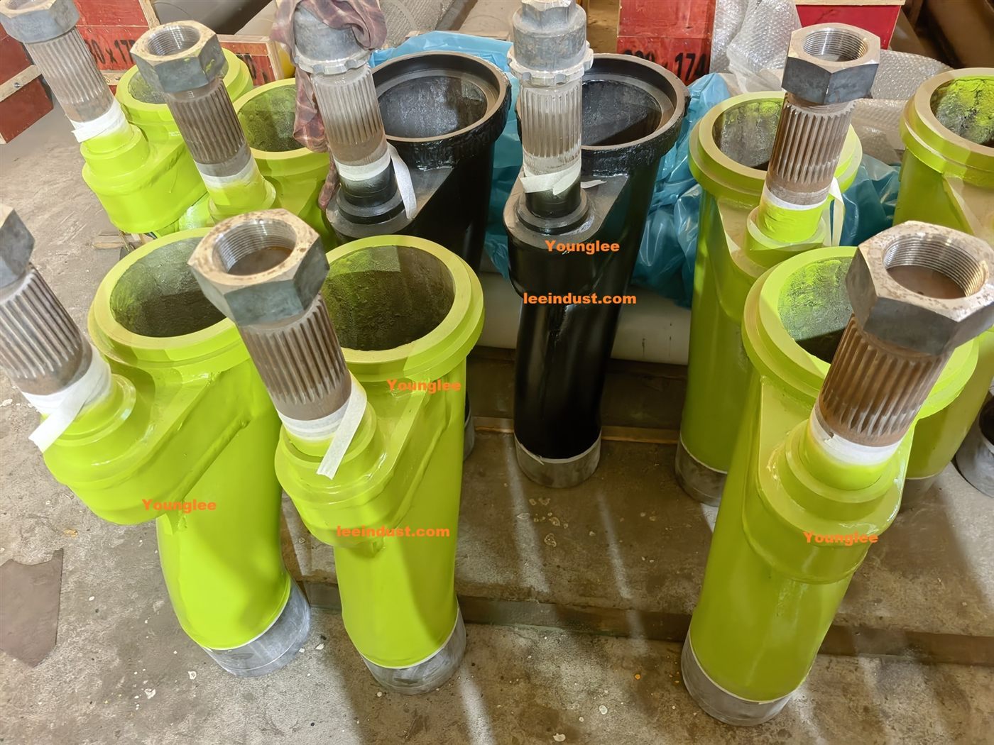
Concrete pump wear ring adjustment is not simply a matter of tightening a nut until leakage stops. On many S-valve pumps, the adjustment establishes the axial position or preload that lets a wear ring remain in contact with the spectacle wear plate. A thrust ring, rubber spring, or related compensation element may then take up limited, reasonably uniform wear during service. If the contact is one-sided, the spring has lost resilience, the shaft support is loose, or the adjustment range is exhausted, more tightening will not restore the sealing geometry.
This distinction matters because manuals use the words gap, clearance, play, and adjustment for different measurement locations. A value from another pump can therefore be both accurately quoted and completely wrong for the machine being serviced. The correct target, measuring point, locking method, and test procedure must come from the manual for the exact pump model and valve configuration.
What does an S-valve wear ring actually seal?
In a typical twin-cylinder pump, the S-valve alternately connects each material cylinder to the outlet. The spectacle wear plate is mounted at the hopper-side cylinder openings, while the wear ring sits at the inlet of the S-valve. Putzmeister’s description of its S-valve wear system also identifies a thrust ring between the wear ring and the valve entry. The exact hardware varies, but the operating requirement is the same: the moving ring must meet the stationary plate closely enough to limit paste and pressure loss while still allowing the valve to switch correctly.
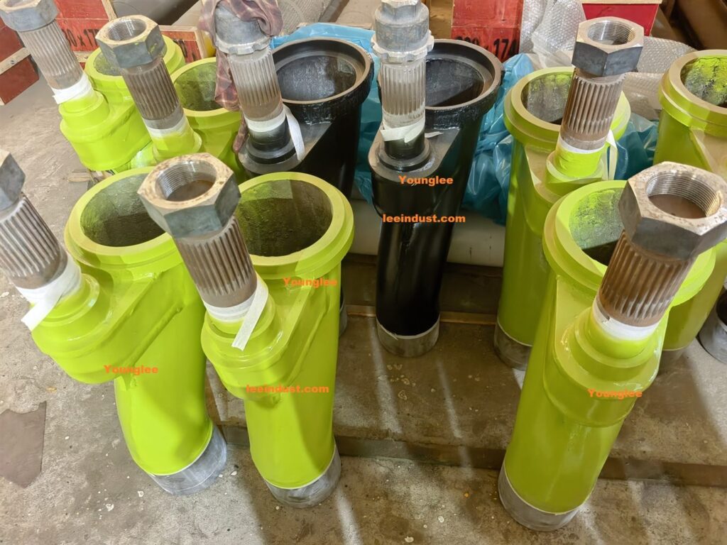
The Concrete Pump S-Valve Assembly is therefore part of the adjustment problem. Its shaft position, bearing support, inlet face, shift linkage, and end positions define where the ring approaches the plate. The ring and plate cannot compensate for a valve body that is being held at the wrong angle or moving on a worn axis.
Positive contact does not mean that every design should be clamped with the greatest possible force. Excessive preload can increase drag, loading, heat, or wear, and it may prevent the valve from settling as intended. Insufficient contact allows cement paste and fine material to pass through the interface. The approved setting is an engineering balance built into one valve design, not a universal rule for all concrete pumps.
How does automatic wear compensation work?
Automatic compensation maintains contact over a limited range; it does not measure wear or correct the valve’s geometry. In designs using a thrust ring, rubber spring, pressure spring, or similar resilient element, the component applies axial force behind the wear ring. As the two contact faces lose a small amount of material reasonably evenly, the ring can move forward within the available travel and continue to meet the plate.
Putzmeister describes an automatic wear ring that compensates for uniform wear and helps retain the concrete-side seal. The word uniform is important. A spring can advance a ring; it cannot make a tilted shaft concentric, flatten a deeply grooved plate, rebuild a chipped carbide sector, or remove hardened concrete trapped behind the ring.
Manual adjustment and automatic compensation often work together. The service adjustment places the mechanism within its designed working range. The resilient element then deals with limited wear between inspections. Once the manual setting reaches its limit, or the compensation element no longer has useful travel or elasticity, the assembly needs inspection and usually parts replacement—not extra force on the adjuster.
Which gap are you measuring?
Before touching an adjusting nut, label the two faces or features between which the measurement is taken. Three different dimensions are commonly confused.
| Measurement | What it describes | Why confusion is costly |
|---|---|---|
| Wear ring-to-wear plate contact or visible gap | The concrete-side sealing interface | A visible opening may allow slurry backflow, but the permissible condition and inspection position depend on the valve design. |
| Wear ring-to-S-valve end-face distance | Space available for a rubber spring, thrust ring, or compensation travel in some S-valve designs | This installation dimension is not automatically the same as the sealing-face gap. |
| Valve-shaft axial play or adjuster position | The location and freedom of the valve body within its supports | Changing it can affect alignment, bearing load, and the position of the complete valve—not just wear-ring contact. |
Model-specific manuals demonstrate why the distinction is necessary. A published SANY HBT9028CH-5S manual specifies a 4 mm distance between the cutting ring and the S-tube end face during its assembly procedure. That is a spring-space or installation relationship; it should not be read as permission for a 4 mm opening between the ring and spectacle plate. A REED-hosted operation manual for another S-tube design instead instructs the technician to tighten an adjusting screw until there is no gap and then release it by at least one-sixth of a turn before securing the lock. These values describe different mechanisms and procedures.
Rock-valve documentation adds another useful warning. A Schwing S 20 manual discusses a visible 1.0–1.5 mm limit before rotating its cutting ring by 90 degrees. That instruction belongs to a specific Rock Valve configuration, not to every S-valve. Copying it to an unrelated assembly would confuse both the valve architecture and the measurement location.
When is adjustment appropriate—and when is replacement the better decision?
Adjustment is reasonable when the machine’s manual provides a defined procedure, the components remain within their wear limits, contact is broadly even, the valve support is stable, and the adjuster still has usable range. It is not a repair for every symptom that resembles leakage.
| Observation | What it can indicate | What to verify before deciding |
|---|---|---|
| Paste or concrete is forced back into the hopper during the delivery stroke | Loss of sealing at the ring/plate interface | Cleanliness, contact pattern, plate and ring grooves, valve end position, piston filling, and whether the symptom occurs on one or both sides |
| Output has fallen but stroke rate appears normal | Internal loss at the valve interface or incomplete cylinder filling | Compare actual ram travel, hopper feed, concrete consistency, line condition, and valve sealing; output loss alone does not identify the part |
| The adjuster has reached its stop | Available take-up range may be exhausted | Wear-part thickness, spring or thrust element condition, shaft location, and the model’s replacement criteria |
| Leakage returns soon after adjustment | Uneven wear, weak spring, contamination, loose support, or incomplete valve seating | Mark the contact pattern and inspect the shaft, bushings, valve face, linkage, and both commanded positions |
| The ring contacts heavily on one sector but opens on another | Misalignment, distortion, shaft/bearing clearance, or non-flat mating parts | Runout, support condition, mounting-face cleanliness, plate seating, and valve-body condition |
| Switching becomes tight or harsh after adjustment | Excess preload or interference is possible | Stop the test and confirm the manual procedure, free movement, actuator/linkage condition, and correct locked position |
REED’s B20 manual makes the service limit practical: periodic S-tube adjustments may improve sealing as the wear interface deteriorates, but the components eventually need replacement. It identifies concrete buildup on the S-tube, deep grooves, noticeably reduced output, and material being forced back into the hopper as reasons to inspect for adjustment or parts. Those observations justify an inspection; they do not by themselves prove that turning the adjuster is the correct action.
Why can tightening fail to stop hopper backflow?
Tightening fails when the problem is no longer a simple, uniform loss of axial contact. A deeply grooved plate provides leakage paths even if average contact pressure increases. A chipped ring cannot recreate a continuous sealing line. Hardened concrete behind a floating ring can consume its travel or hold it at an angle. A tired rubber spring may compress without providing the intended restoring force.
Shaft and bearing condition are equally important. Radial clearance can let the ring approach the plate off-center, while excessive axial movement changes the relationship among the valve, thrust element, ring, and plate. If the valve does not reach its full commanded position, the ring may contact the bridge or port edge instead of seating concentrically. More adjuster force can conceal free play during a static check without correcting what happens dynamically.
Changeover timing can accelerate the same wear. A peer-reviewed study of concrete-pump commutation reported high-velocity concrete passing through the opening between the spectacle plate and cutting ring during switching, producing erosion wear. The study is not an adjustment manual, but it supports an important diagnostic point: a recurring washout track can reflect switching sequence and leakage duration as well as static clearance.
A safe inspection sequence before adjustment
The hopper, S-valve, shift cylinders, and hydraulic accumulator create crushing and stored-energy hazards. Inspection inside the hopper must follow the pump manufacturer’s shutdown, lockout, pressure-release, and verification procedure. Never rely on a stopped engine alone, and never enter a hopper or reach into a valve path merely because the controls appear inactive.
- Record the operating symptom before cleaning. Note whether backflow occurs on one stroke or both, whether the output loss is progressive, whether switching has changed, and whether the complaint depends on pressure or mix.
- Isolate the machine using the exact OEM procedure. Release stored hydraulic and accumulator energy, secure moving equipment, and verify the required zero-energy state.
- Clean the complete contact area. Putzmeister operating instructions call for checking the wear ring and spectacle wear plate after cleaning. Residue can hide grooves and can also create false contact.
- Inspect both valve positions. Photograph the ring and plate with orientation marks. Record grooves, carbide loss, chips, polished sectors, paste tracks, and any difference between the two cylinder ports.
- Check the support and compensation parts. Look for shaft movement, damaged locking hardware, contaminated spring pockets, loss of rubber resilience, thrust-ring damage, and evidence that the valve is not reaching an end position.
- Identify the exact adjustment dimension. Use the current manual for the model, serial range, and installed valve. Confirm where the gauge is placed and whether the instruction refers to face contact, spring space, or shaft play.
- Adjust and lock only as specified. Use the OEM tool, sequence, torque, locking device, and allowable range. Do not substitute another model’s turns, gap, or visual rule.
- Perform the prescribed test. First verify unobstructed movement under the manufacturer’s safe commissioning procedure, then watch for equal seating, normal switching, leakage, abnormal load, and loosening of the locking arrangement.
What should be checked after adjustment?
A static gap check is incomplete. The valve must switch to both sides without binding, and the adjuster must remain positively locked. Confirm that the actuator and linkage are not being used as unintended mechanical stops. During an approved low-speed test, compare left-to-right and right-to-left behavior. One-sided backflow or impact is more consistent with position, alignment, or localized wear than with a simple uniform loss of preload.
Do not judge success only by a quieter hopper. Record whether delivery output, stroke completion, pressure behavior, and material return improve under comparable conditions. If the setting quickly changes again, preserve the evidence and investigate the spring/thrust element, wear thickness, shaft supports, and locking hardware. Repeated adjustment is data; it is not a maintenance strategy.
What information should accompany a wear-part quotation?
Wear plates and rings are frequently sold under broad names such as spectacle plate, glasses plate, wear plate, cutting ring, wear ring, thrust ring, rubber spring, or pressure spring. Marketplace listings confirm that these terms are used across multiple brands and nominal sizes, but a brand name or nominal bore alone does not prove interchangeability.
A useful RFQ should include the pump manufacturer, exact model, serial or production range, trusted part numbers, valve type, and photographs of the installed orientation. Identify whether the requested scope includes only the ring and plate or also the thrust/rubber element, seals, fasteners, locking hardware, shaft bushings, and transition components. Add measured dimensions with the measurement locations shown, plus photographs of the wear pattern before the parts are cleaned or discarded.
If adjustment is already exhausted, state that explicitly. If a new ring and plate wore rapidly, include the hours or pumped volume only as operating history—not as a universal service-life expectation—and describe concrete type, pumping pressure conditions, previous adjustment history, valve-support repairs, and the observed failure pattern.
Frequently asked questions
Does automatic compensation mean the wear ring needs no inspection?
No. Compensation has finite travel and works best with uniform wear and stable geometry. Cleaning, contact-pattern inspection, support checks, and the model’s scheduled maintenance requirements still apply.
Can a worn rubber spring cause leakage even when the ring and plate look usable?
It can. If the resilient element no longer supplies the designed axial force or freedom of movement, apparently serviceable faces may not remain in effective contact. Confirm the component against the model-specific manual rather than adding unapproved shims or preload.
Should a visible gap always be removed completely?
No universal answer is safe. Some instructions target positive contact; others define a particular gap, release angle, spring-space dimension, or allowable play at another location. Identify the two measured surfaces and use the manual for the installed configuration.
Can the cutting ring be rotated instead of replaced?
Some designs permit scheduled rotation to distribute localized wear, particularly certain Rock Valve arrangements. Other assemblies use different wear components and adjustment methods. Rotate a ring only when the applicable OEM procedure permits it and the part remains within its inspection limits.
Conclusion
Concrete pump wear ring adjustment is best understood as restoration of a specified working relationship, not as a generic cure for hopper leakage. First determine which clearance the manual is discussing. Then separate normal compensation travel from worn faces, a weak spring or thrust element, shaft movement, incomplete valve travel, and timing-related erosion. If contact remains uneven or the adjuster has reached its limit, the correct decision is usually broader inspection and parts planning rather than further tightening.
Technical references
- Putzmeister M36 product and S-valve wear-system description
- REED B20 operation and maintenance manual
- REED-hosted 36R4XT operation manual
- SANY HBT9028CH-5S operation and maintenance manual copy
- Putzmeister P 715 operating instructions
- Schwing S 20 operating instructions, cutting-ring inspection
- Applied Sciences: commutation timing and erosion wear in concrete pumping systems