Concrete Pump Parts Knowledge
How to Replace Concrete Pump Piston Cups: Inspection, Fit, and Safe Recommissioning
Replacing a concrete pump piston cup is not simply a matter of pulling out a worn rubber part and pushing in a new one. The mechanic must position the ram using the pump’s approved procedure, remove every source of stored energy before entering the water box or material-cylinder area, keep the new cup square during installation, and decide whether the cylinder bore is fit to run against it. Missing any one of those checks can turn a planned wear-part change into an injury, a damaged seal, or another shutdown after only a short return to service.
This guide explains the decision points that apply across many twin-cylinder pumps. It is not a substitute for the service manual for the exact pump model. Access arrangements, ram-positioning methods, fasteners, tightening values, lubricants, sealants, and recommissioning steps differ materially among manufacturers and machine generations.
Confirm that the piston cup is the part that needs attention
Slurry or increasingly coarse sand in the water box is a strong reason to inspect the piston-to-cylinder interface. Multiquip’s Mayco manual identifies the passage of larger sand and cement particles into the lubrication box as a replacement trigger. REED’s troubleshooting guidance similarly connects slurry in the water box with worn or loose piston cups, but it also lists excessive cylinder wear as a possible cause. That second point prevents a costly diagnostic shortcut: installing a new cup does not restore a scored, tapered, corroded, or out-of-round bore.
Low output is even less specific. A worn piston cup can allow bypass or reduce cylinder filling, but hopper feed, concrete consistency, pump speed, transfer-valve sealing, short stroking, and hydraulic faults can produce similar complaints. Treat performance changes as evidence to investigate, not as proof that one replaceable part has failed.
| Observation | Possible mechanism | What to verify before ordering |
|---|---|---|
| Slurry repeatedly appears in the water box after proper cleaning | Piston cup leakage, a loose piston assembly, or an excessively worn cylinder | Compare both sides; inspect cup retention, the removed cup, and the bore |
| One cup wears much faster than the other | Local bore damage, uneven geometry, contamination, or an assembly/alignment problem | Record left/right wear patterns and map bore diameter by depth and direction |
| Output declines without obvious water-box contamination | Incomplete filling, valve-side leakage, short stroke, hydraulic trouble, or cup wear | Check operating history and the complete pumping cycle before disassembly |
| A new cup squeals | Initial break-in or installation distortion | Check the applicable manual, mounting condition, water-box fluid, heat, and persistent leakage |
Why there is no safe universal piston-cup replacement sequence
Official procedures show how different the job can be. A current Mayco LS-series manual removes the hopper with an approved lifting device before positioning a piston at the end of the material cylinder. Alliance service information for certain truck pumps instead positions a ram and removes a spacer flange so the cup can be brought into the water box. These are not interchangeable variations of one Internet procedure; they reflect different pump layouts and hydraulic circuits.
The exact manual also controls how the ram is held, which energy sources are isolated, whether fasteners must be renewed, how the seal stack is oriented, what assembly lubricant or sealant is permitted, and how bolts are tightened. Copying a torque value, valve position, or ram-changing method from another model is unsafe even when the piston cups look similar.
Build the job around the machine identity
Before the pump is opened, record the manufacturer, model, serial number, pump-kit configuration, and the revision of the operating or service manual. Confirm the piston-cup part number and determine whether the ordered item is only the flexible cup or a kit containing guide rings, O-rings, felt or lubrication components, plates, retainers, and specified replacement hardware.
Photograph the installed arrangement before disassembly. Mark the left and right assemblies, orientation, spacers, and any parts that can be reversed. Prepare clean trays so components from the two sides are not mixed. Verify that the specified lifting equipment, supports, alignment tools, calibrated torque tool, cleaning materials, lubricant, and sealant are available before the pump is immobilized.
Parts buyers should not rely on “DN200 piston” or a pump brand alone. Market listings use overlapping terms such as piston cup, concrete piston, delivery piston, piston ram, cup seal, and piston seal. A nominal diameter does not identify the mounting arrangement or the complete stack. For an accurate quotation, supply the exact pump model and serial, OEM reference if available, material-cylinder bore, old-part dimensions and photographs, fastening style, guide and lubrication parts required, and quantity.
Stored energy is the first inspection point
A stopped engine does not make the concrete end safe. Concrete pumps may retain hydraulic accumulator energy, pressure in a hydraulic tank or circuit, mechanical movement potential, and pressure in the material system. The hopper agitator and transfer valve also create crushing and amputation hazards near the same work area.
Use the manufacturer’s shutdown, pressure-release, lockout, and verification procedure for that machine. Multiquip explicitly requires the accumulator circuit to read zero before maintenance in the cylinder area. Other models add machine-specific valves, ram-change controls, supports, interlocks, PTO isolation, battery isolation, or hydraulic-tank depressurization. A qualified mechanic should verify the zero-energy state; the position of a control lever or the absence of engine noise is not verification.
Do not reach through an opened grate, into the water box, or into a material cylinder until the approved isolation is complete and protected against reactivation. If the procedure requires temporarily powering the machine to position a ram, perform that controlled positioning phase exactly as the manual specifies, keep personnel out of the hazard zone, and then repeat the full isolation and zero-energy verification before hands or tools enter the area.
Use the removed cup as a failure record
Cleaning and discarding the old parts immediately throws away useful evidence. Label each removed cup by side and orientation. Examine the sealing edge, body, guide components, plates, O-rings, retainers, and fasteners together.
A broadly uniform worn lip can be consistent with normal service exposure. A cut, torn edge may point to a burr, hardened residue, damaged bore, or installation injury. One-sided polishing or deformation suggests that the cup did not run concentrically, although the cause still needs verification. A loose or damaged retaining arrangement can imitate ordinary cup wear while allowing movement that a new seal alone will not correct.
Clean the accessible bore without scratching its working surface. Inspect for hardened concrete, chrome damage, scoring, corrosion, a sharp entry edge, and localized polishing. If service history shows short cup life, repeat failures on one side, or visible geometry changes, measure the bore rather than judging it by sight. A bore map at multiple depths and orientations can distinguish general enlargement from taper or ovality. Acceptance limits must come from the correct OEM drawing, manual, or approved repair specification.
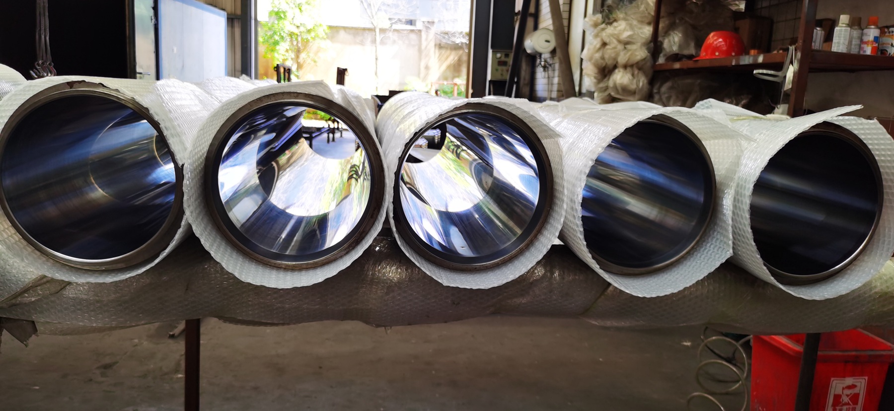
The new cups will only perform as intended if the working surfaces of the Concrete Pump Delivery Cylinders can support sealing contact. A new flexible part may temporarily mask a worn bore, but it cannot correct the cylinder’s geometry or replace missing surface material.
Installation quality is mainly alignment, cleanliness, and specification control
Compare every new component with the removed assembly before applying lubricant or sealant. Confirm the relevant diameters, overall height, bolt pattern, guide parts, plate arrangement, and sealing-lip direction. Check that the part number and material designation match the purchase record. Do not assume that color identifies an elastomer or polyurethane grade.
Use only the assembly lubricant, oil, grease, and sealant specified for the model. Their functions are different: one may protect the cup during initial entry, another may saturate a lubrication element, and a sealant may belong only on a plate or fastener interface. Extra product in the wrong location can contaminate the water box, interfere with clamping, or conceal a leak.
Guide the assembly squarely into the bore using the approved tooling and method. A cocked cup can fold or cut its sealing edge before the pump makes a stroke. Keep threaded studs, sharp tools, and burrs away from the running lip. Tighten the retaining parts in the prescribed sequence and to the model-specific value; unequal or excessive clamping can distort the cup. REED’s troubleshooting material specifically identifies over-tightened piston-plate bolts as one cause of piston-cup distortion and squeal.
Where the OEM procedure calls for both cylinder cups to be renewed as a pair, do so and preserve the side identification during assembly. Even when only one side shows an obvious defect, inspect the other side under the same criteria. The comparison often reveals whether the problem is ordinary wear or a localized cylinder and alignment issue.
Recommission slowly enough to learn something
Reinstall guards, covers, interlocks, hoses, supports, and the hopper components specified by the manual. Account for tools and removed hardware before power is restored. Establish an exclusion zone for the initial functional check and use the OEM’s approved low-speed or test procedure; do not invent a generic test pressure or number of strokes.
During the first controlled cycles, verify full and symmetrical piston movement, correct changeover, secure fasteners, and absence of hydraulic or water-box leakage. Watch for a cup that enters the bore unevenly, unusual heat, abnormal drag, or persistent squeal. Some new-cup noise can occur during break-in according to REED, but noise combined with heat, contamination, uneven motion, or immediate performance loss warrants shutdown and inspection.
After the prescribed initial check, inspect the water-box fluid again and document the baseline condition. During the next pumping period, compare output rhythm and water-box contamination with the pre-repair record. If slurry returns quickly, do not keep tightening hardware or installing cups repeatedly. Recheck bore condition, piston retention, cylinder filling, and valve-side sealing so the repair addresses the mechanism rather than only the visible wear part.
A useful piston-cup change leaves a traceable record
Record the machine identity, operating hours if reliable, symptoms, left/right cup condition, bore observations and measurements, installed part numbers, batch or supplier reference, renewed hardware, lubricant and sealant, tightening data, manual revision, and recommissioning results. Keep photographs of the old wear pattern and the cleaned bore.
That record turns the next cup change into a comparison rather than another guess. It also helps a distributor or repair workshop distinguish a consumable reaching normal wear from a cylinder-side defect that is repeatedly damaging new parts.
Conclusion
A concrete pump piston cup should be replaced as part of a controlled wear-system inspection. Confirm the symptom, identify the exact pump configuration, follow its ram-positioning and zero-energy procedure, preserve the old cup as evidence, inspect the cylinder bore, and install the new stack with the specified orientation, lubricant, hardware, and tightening method. The decisive question is not merely whether a new cup fits into the bore. It is whether the cup, cylinder surface, retaining assembly, and recommissioning result show that the sealing pair is ready for another service interval.