Concrete Pump Parts Knowledge
Concrete Pump Material-Cylinder Tie Rods: Loose-Nut Diagnosis and Ordering Checks
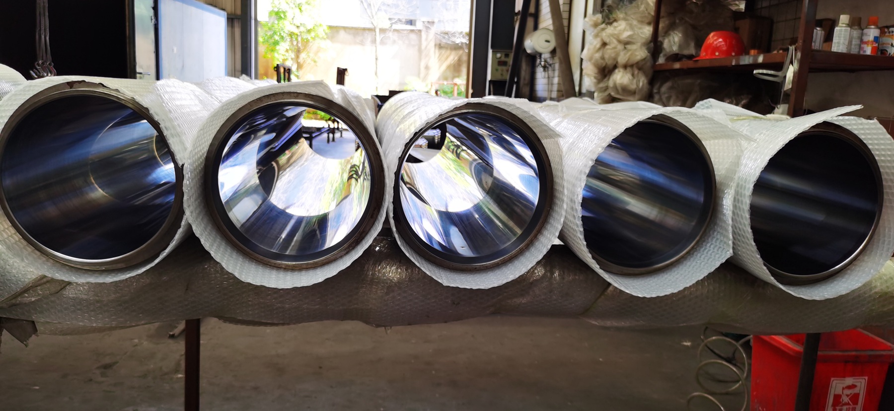
A concrete pump material-cylinder tie rod is part of the clamped structure that keeps the concrete-side cylinders and their adjoining interfaces in the intended installed relationship. If a rod, nut, seating face, or adjacent support loses integrity, the result can be joint movement, fretting, seal disturbance, or a change in cylinder alignment. A loose nut is therefore evidence that deserves investigation—not permission to apply an arbitrary torque and continue pumping.
What does a material-cylinder tie rod do?
Depending on the pump design, long threaded rods help clamp together some combination of the hopper or valve housing, material cylinders, water box, hydraulic-cylinder support, end plate, and frame-mounted brackets. The exact load path is model-specific. The rod is not simply a convenient mounting bolt: its tension creates clamp force across the joined components.
That distinction matters. In a properly designed and assembled preloaded joint, the clamped faces carry much of the service load while the fastener maintains compression. If clamp load falls far enough for interfaces to separate or slide, the joint can experience impact, fretting, leakage, and a larger cyclic load range in the rod. NASA’s Fastener Design Manual explains the general relationship among fastener preload, external loading, joint separation, and fatigue. It is a useful engineering principle, but it does not provide a concrete-pump torque specification.
OEM parts books show why the component cannot be identified generically. A REED C-series manual lists two different tie-rod sizes in the same pumping-train assembly, with different quantities and different nut torques. Another REED cylinder assembly identifies four concrete-cylinder tie rods, while a Mayco LS300G maintenance procedure refers to two tie-rod nuts plus four eyebolt nuts securing the hopper. “Concrete pump tie rod” is therefore a family name, not a complete purchasing description.
Do not confuse three different kinds of rod
Parts inquiries often become ambiguous because several long components can be called rods. Before measuring or ordering, identify the component by function and location.
| Component | Primary function | Useful identifying evidence |
|---|---|---|
| Material-cylinder or pump-train tie rod | Clamps structural interfaces around the concrete-side pumping train | Runs outside the cylinder barrels; threaded ends carry nuts or engage a fixed feature |
| Hydraulic-cylinder tie rod | Holds the end caps and barrel of a tie-rod-style hydraulic cylinder together | Belongs to one hydraulic cylinder assembly and follows its barrel |
| Piston rod, connecting rod, or coupler | Transfers reciprocating force from the hydraulic drive side to the concrete piston | Moves through the water-box region and connects to the delivery piston |
The distinction affects both diagnosis and safety. A stationary external rod with a loose nut presents a different problem from a moving piston coupling or an internal hydraulic-cylinder fastener. Send location photographs with every inquiry instead of relying on translated terminology alone.
What can a loose or damaged tie rod cause?
Loss of clamp force can allow an interface to move under alternating pumping loads. Possible consequences include polished contact marks around a nut or washer, reddish or dark fretting debris, witness-mark movement, recurring seal leakage, opening of a flange gap, or a change in the installed relationship between a material cylinder and the connected housing. The consequence depends on which components that rod clamps.
These observations do not prove that the rod itself caused the fault. Debris trapped between mating faces, damaged pilots, a distorted bracket, corrosion under a washer, an incorrect seal stack, unsuitable fastener hardware, frame damage, or an assembly that was forced into position can unload an otherwise sound rod. A nut may also appear loose because the joint settled after assembly, a locking feature failed, or the thread was damaged.
| Observation | Possible mechanism | What to verify before deciding |
|---|---|---|
| Witness marks no longer align | Nut rotation or joint movement may have occurred | Original marking method, washer movement, thread condition, and OEM locking arrangement |
| Fretting debris or polished arcs at a seat | Relative motion may be occurring at a clamped interface | Flatness, burrs, corrosion, surface damage, and adjacent support condition |
| Recurring leakage after seal replacement | Interface movement or poor seating may be disturbing the seal | Correct seal, groove condition, flange geometry, pilot engagement, and cylinder alignment |
| One cylinder shifts as hardware is tightened | The structural stack may be pulled into a strained position | Clean mating faces, supports, pilots, rod identity, tightening sequence, and OEM alignment test |
| Damaged threads or a necked, bent, or corroded rod | Load capacity or reliable preload may be compromised | Replacement criteria and part specification from the manufacturer |
If directional piston or bore wear appears at the same time, treat it as a separate diagnostic question. The material-cylinder alignment check should evaluate the installed axis through the full stroke using the model-specific method. Tightening tie rods cannot restore a worn bore or prove that alignment is acceptable.
Why is “just retorque it” an unsafe diagnosis?
Torque is only an indirect way of producing fastener tension. Thread friction, nut-face friction, coatings, lubrication, corrosion, reused hardware, washer condition, and tool accuracy all affect the relationship between applied torque and clamp load. Changing lubricant or replacing one nut with a different finish can change the achieved tension even when the wrench setting is unchanged.
For that reason, do not borrow a value from another pump or use a generic torque chart. The REED C-series example is especially instructive: one manual shows different sizes and specified values within one assembly. Those published values apply only to the identified model, revision, hardware, and procedure. They are not universal LeeIndust recommendations.
A credible repair answers why clamp load was lost before restoring it. It also establishes whether the rod, nut, washer, thread engagement, mating faces, supports, pilots, seals, and connected parts remain serviceable. If the manufacturer requires replacement rather than reuse, a staged sequence, calibrated tooling, lubrication in a defined condition, locking hardware, or an alignment verification after final bolt-up, those instructions control.
How should a workshop inspect the joint?
Begin with the pump isolated under the manufacturer’s procedure. Material-cylinder service may place personnel near the hopper, valve, water box, or heavy suspended components. The ACPA mechanics safety guide requires control of hydraulic and stored energy and warns that hopper, valve, agitator, accumulator, and water-box areas contain crushing and amputation hazards. The machine manual must define the safe state and lifting method.
Before loosening hardware, record the installed condition. Photograph every rod end and nut, identify left/right and viewing direction, capture witness marks, and measure any visible interface gap without disturbing it. Note corrosion, damaged flats, washer indentation, cracked paint lines, fretting debris, seal tracks, and whether a bracket or flange appears to be carrying load unevenly.
After safe disassembly, inspect the complete load path rather than only the threads. Mating faces should be clean enough to reveal burrs, concrete residue, corrosion, peening, distortion, or damaged pilots. Check whether holes have elongated and whether washers or seating faces have yielded or galled. A replacement rod installed against a damaged seat may not retain the intended clamp condition.
Compare the old parts with the exact OEM record. The REED 40-series cylinder drawing separates the concrete-cylinder tie rods, nuts, concrete cylinders, flush box, and hydraulic-cylinder assemblies. The REED C-series manual shows another arrangement with two tie-rod sizes. These are useful examples of configuration differences, not interchangeable repair instructions.
What information is needed to order a replacement tie rod?
A reliable RFQ should connect the rod to a verified machine configuration and define every feature that controls fit. Include:
- equipment manufacturer, exact model, pump-kit designation, serial number, and manual revision;
- verified OEM or previously accepted part number, including every suffix;
- installed location and quantity, supported by overview and close-up photographs;
- overall length with the two measurement faces clearly marked;
- rod-body diameter and any reduced, shouldered, relieved, or unthreaded sections;
- thread form, nominal diameter, pitch, handedness if unusual, threaded length at each end, and whether both ends are identical;
- nut, washer, spacer, sleeve, bracket, or locking feature associated with each end;
- surface condition or coating documented by the applicable drawing or parts record; and
- whether the quotation includes one rod, a positional set, or all related hardware.
Do not infer strength grade, heat treatment, material, or coating from appearance. Do not assume a rod with matching diameter and pitch has the correct tensile capacity, effective length, shoulder geometry, or thread engagement. If the old rod is bent or stretched, its overall length is evidence of condition—not automatically the manufacturing target.
When a tie-rod issue is found during replacement of a Concrete Pump Delivery Cylinder, keep the cylinder identification and the structural-hardware identification as separate line items. Bore size and cylinder length do not identify the tie rods. LeeIndust’s delivery-cylinder ordering guide covers the barrel dimensions and interfaces that should be documented alongside the hardware.
Does one loose nut mean every tie rod must be replaced?
Not automatically. Replacement scope depends on the design, the reason preload was lost, the condition of every rod and seat, and the OEM service rule. A nut that backed off without thread or rod damage presents a different finding from a rod with corrosion loss, bent geometry, yielded threads, or an unknown substitute part. Because rods in one assembly may have different sizes or functions, a “replace all identical rods” rule should not be invented without model-specific support.
Can new tie rods correct material-cylinder misalignment?
Only if defective or incorrect rods were part of the verified cause and the remaining structure is serviceable. New rods cannot correct a distorted frame, damaged register, dirty mating face, unsupported hopper, worn bore, or incorrect cylinder interface. Alignment must be checked by the manufacturer’s specified method after the relevant interfaces are assembled and tightened.
Should tie-rod length be checked in inches or millimetres?
Use the unit of the controlling drawing or manual and preserve the original precision. If a source dimension is in inches, retain every decimal place or fraction exactly as supplied before any conversion to millimetres. A rounded source value can create a meaningful conversion error when multiplied by 25.4. Label the measurement faces and distinguish an as-removed measurement from a specified new-part dimension.
Conclusion
Concrete pump material-cylinder tie rods maintain clamp force across model-specific pumping-train interfaces. When a nut moves, a seat frets, or a flange begins to separate, the correct response is to preserve the evidence, inspect the complete load path, identify why preload was lost, and follow the exact OEM assembly and torque procedure. A useful purchase record combines machine identity, part number, location, dimensions, thread details, related hardware, and clear photographs. Treating the rod as a generic length of threaded steel can turn a small hardware discrepancy into repeated leakage, alignment trouble, or structural movement.
Technical sources
- REED C70SS/C90SDR technical manual: model-specific pumping-train tie-rod sizes, quantities, hardware, and torque callouts.
- REED 40-series parts manual: concrete-cylinder tie rods and their relationship to the flush box, cylinders, and drive assemblies.
- Multiquip Mayco LS300G operation manual: a different hopper-retention arrangement and model-specific service procedure.
- NASA Fastener Design Manual: preload, joint separation, fatigue loading, and torque variables in threaded fasteners.
- ACPA Safety Procedures for Concrete Pump Mechanics: hazardous-energy controls for pump maintenance.