Concrete Pump Parts Knowledge
Concrete Pump Hydraulic Tank Breather: Clogged Symptoms and Replacement Data
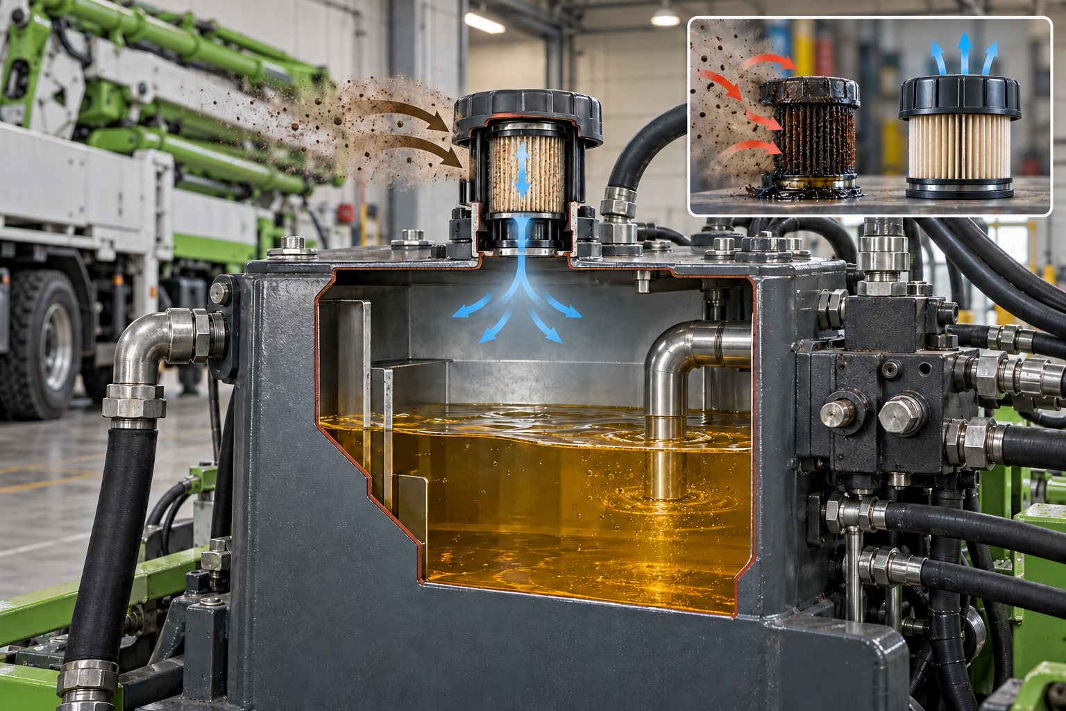
A concrete pump hydraulic tank breather should admit and exhaust enough air for reservoir-level changes while keeping airborne dirt—and, where specified, moisture—out of the oil. A clogged, saturated, damaged, or incorrectly matched breather can contribute to reservoir vacuum or pressure, pump-inlet starvation, oil leakage, and contamination. It is not, however, a stand-alone diagnosis: foaming at the cap, a noisy pump, or hot oil can also come from incorrect oil level, suction leaks, return-flow aeration, cold oil, blocked strainers, or another hydraulic fault.
This article explains how to separate those mechanisms, what to inspect safely, and which data must be confirmed before ordering a replacement filler-breather or breather element. The exact construction and maintenance method remain model-specific.
What Does a Hydraulic Tank Breather Do?
As hydraulic actuators move, the quantity of oil stored in the reservoir can change. Thermal expansion, return flow, leakage flow, and machine attitude can also change the oil level and headspace condition. Unless the reservoir is deliberately designed as a pressurized system, the breather provides a controlled path for air to move in and out instead of passing through gaps, seals, or an open filler neck.
The breather is an air filter, not a return-line oil filter. A return filter removes contamination carried by oil returning from the circuit. A breather filters the air exchanged with the reservoir. The two devices protect different entry paths and are not interchangeable. This distinction is documented in concrete-pump manuals: the official REED ST48 manual, for example, identifies a filler-breather, return filter, high-pressure filter, and suction filters as separate components.
Some assemblies combine a filler cap, air-filter media, dipstick, splash control, and an oil-filling strainer. Others use a separate spin-on air element or a desiccant cartridge. Manufacturers such as MP Filtri offer pressurized and non-pressurized versions, several mounting arrangements, replaceable elements, and widely different airflow capacities. A cap that physically fits the opening can therefore be hydraulically wrong.
What Can a Clogged Breather Cause?
A restricted breather resists the air movement needed as the reservoir oil level changes. When oil leaves the tank faster than air can enter, reservoir pressure can fall below ambient pressure. Depending on the tank and pump-inlet arrangement, that restriction may add to suction losses and can contribute to abnormal pump noise, aeration, reduced response, or heat. When return flow raises the level faster than air can leave, reservoir pressure can rise and expose weak gaskets or seals.
The word can matters. A breather restriction does not prove that the hydraulic pump, a valve, or an actuator is damaged. The symptom must be tested against oil temperature, oil level, actuator position, recent maintenance, and the rest of the inlet path. REED’s concrete-pump troubleshooting guidance includes a clogged breather among possible causes of hot hydraulic oil, but it also lists cooler faults, loaded filter elements, suction-strainer restriction, relief-valve problems, prolonged high-pressure operation, and low oil level. That is a diagnostic list, not permission to replace the breather and stop investigating.
| Observation | Breather-related possibility | Evidence to check before deciding |
|---|---|---|
| Pump noise is strongest as cylinders extend | Insufficient air entering the reservoir may add inlet restriction | Breather condition, reservoir pressure/vacuum if the OEM provides a method, oil viscosity and temperature, suction hose, valves, and strainers |
| Oil leaks at a tank cover or gasket | Air cannot leave freely, or the wrong pressurizing cap is installed | Exact leak origin, oil level, actuator position, return flow, cap specification, gasket condition, and tank damage |
| Oil or foam emerges from the cap | Media may be oil-saturated, but the breather may only be where another fault becomes visible | Overfill, aeration, return-line position, slope, sloshing, thermal expansion, and recent refill history |
| Oil repeatedly becomes dusty or has rising particle counts | Missing, damaged, bypassed, or inefficient breather media may admit airborne dirt | Filler-neck sealing, access covers, rod wipers, maintenance practices, new-oil cleanliness, and laboratory trend data |
| Moisture control media changes color quickly | Desiccant is reaching its indicated capacity or oil mist is contacting it | Manufacturer’s indicator meaning, ambient humidity, washdown exposure, reservoir temperature cycles, mounting, and oil carryover |
| Hot oil follows a breather change | Replacement may have inadequate airflow or the wrong valve setting | Installed part number, airflow/pressure-drop data, pressurized versus open-reservoir design, and other heat sources |
Does Oil Coming Out of the Breather Mean It Is Clogged?
No. Oil at the breather is an observation, not a root cause. An overfilled reservoir may have insufficient headspace when oil warms or cylinders return. A machine parked or operating on a slope can move oil toward the cap. Aerated oil occupies more apparent volume and may carry foam into the headspace. A return line that discharges improperly can agitate the reservoir, while a missing splash guard or wrong cap can make slosh losses worse. Some tanks are intentionally maintained at a small positive pressure, in which case the specified valve arrangement becomes part of the diagnosis.
Record the oil level at the machine condition stated by the OEM. Actuator position matters because rod volume changes can move oil between cylinders and the reservoir. Compare cold and stabilized conditions, and note whether the event occurs during one function, during transport, on a grade, or after a refill. If the oil is foamy or cloudy, use the separate hydraulic-oil foaming diagnostic workflow; replacing a wet breather will not correct a suction leak or an aerating return.
How Does the Breather Affect Contamination Control?
Every time outside air enters an open reservoir, it can carry dust. Construction equipment adds concrete dust, road dirt, washdown, rain exposure, and frequent temperature changes. If the cap is removed for filling, contamination can also fall directly through the opening. The REED ST48 instructions tell technicians to clean around the filler opening, add clean hydraulic fluid through appropriate filtration, and replace the cap immediately. Those details matter because even a capable breather cannot protect an uncovered filler neck.
Hydraulic-component manufacturers treat the breather as a measurable filtration device. Parker’s EAB-series data, for example, specifies airflow, filter media, connection, optional pressure indication, and pressure-relief features for individual configurations. The lesson is not that one Parker rating suits a concrete pump; it is that breather selection involves performance data, not appearance alone.
Airborne contamination can eventually reach pumps, valve spools, bearings, seals, and actuators. It may therefore affect valve switching and the oil supplied to Concrete Pump Slewing Cylinders. But contamination found in a slewing-cylinder circuit does not establish the breather as the source. Dirt may also enter through maintenance, dirty new oil, failed rod wipers, opened hoses, damaged tank seals, or component wear. Particle-count trends, filter-debris inspection, and repair history provide stronger evidence than a dusty cap alone.
When Is a Desiccant Breather Appropriate?
A desiccant breather combines particle filtration with media intended to remove moisture from incoming air. It can be useful where humidity, condensation, outdoor storage, temperature cycling, or washdown creates a credible moisture-ingress problem. It is not an automatic upgrade for every concrete pump. The cartridge needs adequate airflow, compatible mounting, protection from direct oil splash, and a service method based on the breather manufacturer’s indicator and the machine environment.
Do not diagnose water in hydraulic oil solely from a desiccant color change, and do not assume a standard particle breather removes water. If oil appears milky, use a representative sample and the OEM or oil supplier’s test requirements. Water can enter through an open filler, damaged covers, condensation, washing practices, or a failed water-to-oil heat exchanger where that design is used. A desiccant unit treats one ingress path; it does not repair another.
Information for Buyer Confirmation
A useful breather request should identify the machine and the reservoir, then define how the existing unit works. Send the supplier the following evidence rather than asking for a generic “concrete pump oil cap”:
- Concrete-pump manufacturer, model, serial number, year, and hydraulic-system variant.
- Whether the breather serves the pumping reservoir, boom reservoir, combined tank, or another compartment.
- OEM breather, cap, element, adapter, and superseded part numbers where available.
- Breather type: filler-breather, separate air element, spin-on element, desiccant cartridge, pressurized cap, or non-pressurized cap.
- Connection form and size: thread standard, flange pattern, bolt circle, filler-neck geometry, adapter, gasket, and sealing surface.
- Required airflow and allowable pressure drop or vacuum/pressure limit from approved machine or breather data.
- Filtration rating and efficiency basis, not only an unsupported “micron” label.
- Pressurization or relief-valve setting if the reservoir is designed to use one.
- Operating temperature, hydraulic-fluid compatibility, and seal material where specified.
- Desiccant or water-resistant media requirement and its condition-indication method.
- Dipstick length and calibration marks, filling strainer, anti-splash feature, lock, chain, guard, or restriction indicator if fitted.
- Maximum installed height and clearance beneath covers, booms, or service doors.
- Environment: concrete dust, road use, humidity, rain, washdown, temperature cycling, and machine inclination.
- Photographs of the cap, mounting, label, filler neck, surrounding clearance, and old gasket before removal.
Airflow is especially easy to overlook. Larger elements offered by industrial suppliers may pass many times the air of compact caps, while pressure drop rises with flow. A finer-looking element is not automatically better if it creates excessive restriction. Likewise, installing a pressurizing cap on a reservoir designed to vent freely—or removing the valve from a reservoir designed for controlled pressure—changes the system. Confirm the intended arrangement from the pump manufacturer’s parts book, hydraulic documentation, and breather data.
Can the Existing Breather Be Cleaned?
Only if the machine and breather manufacturer allow it. The REED ST48 manual includes solvent cleaning and air drying for the documented filler-breather during hydraulic-tank service. That procedure should not be generalized to disposable paper, fine synthetic, spin-on, or desiccant elements. Solvent can damage media, adhesives, seals, or moisture indicators; compressed air can rupture media or drive dirt to the clean side. Some elements must be replaced rather than washed.
Before opening the reservoir, park and secure the machine, stop power, apply lockout/tagout, release stored hydraulic and accumulator energy by the manufacturer’s procedure, allow hot oil to cool, and clean the area around the cap. ISO 4413:2010 addresses hazards associated with hydraulic systems, while the ACPA Mechanics Guide emphasizes manufacturer settings, suitable components, and documented maintenance. Neither source replaces the model-specific service manual.
After service, verify the cap and gasket are seated correctly, the filler neck is closed, the oil level is correct for the specified machine condition, and no new leak develops as functions are operated through the OEM recommissioning sequence. If a restriction or contamination problem recurs, inspect the complete air, oil, and maintenance path. The related hydraulic oil filter replacement guide explains why return, pressure, suction, loop, and breather filters must be identified separately.
What Should Be Recorded After Replacement?
Record the installed part number, element specification, date and machine hours, oil level and temperature, actuator position used for the level check, observed tank pressure or vacuum if an approved test exists, and the reason for replacement. Photograph the removed element and note whether it was dusty, oil-saturated, physically damaged, wet, or at its indicated desiccant limit. Preserve unusual debris or oil samples when a broader failure investigation is under way.
A good record prevents the next technician from treating the new cap as an unexplained substitute. It also helps distinguish normal environmental loading from rapid recurrence caused by excessive oil mist, a badly positioned return, an overfilled reservoir, wash-water entry, or the wrong breather capacity.
Conclusion
The concrete pump hydraulic tank breather is a small component with two separate duties: permitting controlled air exchange and limiting contamination ingress. Diagnose it as part of the reservoir and pump-inlet system, not as an isolated cap. A clogged breather can add restriction; oil at the cap can come from several other mechanisms; and a replacement that fits can still have the wrong airflow, media, connection, or pressure behavior. The defensible approach is to capture the symptom under known operating conditions, verify the complete inlet and reservoir arrangement, match the OEM function, and document the result.