Concrete Pump Parts Knowledge
Concrete Pump Hydraulic-System Flushing After Component Failure
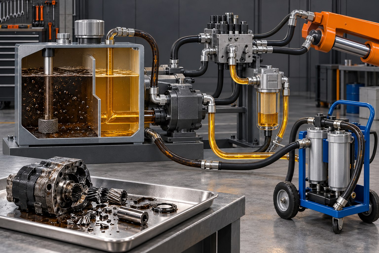
A concrete pump hydraulic system should be considered for flushing when a failed pump, motor, valve, hose, cylinder, or other component may have released debris or degraded fluid into a shared circuit. Draining the reservoir and installing a replacement part is not enough if metal, elastomer fragments, water, sludge, or incompatible oil remains in hoses, manifolds, coolers, cylinders, or low-flow cavities. The correct cleanup scope depends on the failure mode and hydraulic schematic, and the machine manufacturer’s procedure must control the work.
This distinction is commercially important. A new hydraulic pump or Concrete Pump Slewing Cylinder can be damaged by contamination left from the original failure, even when the replacement itself is correct. A documented cleanup plan protects the replacement, helps identify the root cause, and gives the workshop evidence that the machine was ready to return to service.
When Does a Concrete Pump Need More Than an Oil Change?
A full or circuit-specific flush is normally evaluated when contamination could have travelled beyond the failed component. The visible damage is only the starting point. A failure on the pressure side can send particles downstream, while return flow may carry them into the reservoir and then toward other circuits. A filter reduces that risk, but it does not prove every particle was captured; the filter may have entered bypass, ruptured, reached its loading limit, or been located outside the affected path.
| Observation | Contamination concern | Evidence to collect before deciding scope |
|---|---|---|
| Broken pump, motor, bearing, gear, or piston surface | Hard metallic particles may have entered pressure, return, case-drain, cooler, or reservoir paths | Failure debris, filter inspection, schematic, oil sample, magnetic and non-magnetic residue |
| Internally damaged hose or seal | Rubber, polymer, or reinforcement fragments can lodge in orifices, valves, and filters | Hose interior, fracture location, downstream screens, valve symptoms, filter contents |
| Water, wrong fluid, or incompatible top-up | Changing only the tank oil may leave contaminated fluid in cylinders, lines, coolers, and manifolds | Fluid identity, water test, viscosity, service records, sample locations, affected circuits |
| New filter loads rapidly after repair | Debris may still be circulating or a component may still be generating wear particles | Element debris trend, differential restriction, particle-count trend, component inspection |
| External rod-seal leak with no internal break-up | System-wide particle release may be unlikely, but dirt could have entered while the circuit was open | Seal and rod condition, cleanliness controls during repair, retained oil and filter evidence |
An external leak does not automatically justify flushing the entire machine. Conversely, a clean-looking reservoir does not prove that a common circuit is clean. The decision should combine failure inspection, oil and filter evidence, flow-path mapping, and the OEM’s cleanup requirements.
Why Is Draining and Refilling Not the Same as Flushing?
Draining replaces accessible bulk oil; flushing is a controlled cleaning process intended to transport and remove contamination from the affected flow paths. Hydraulic oil remains in long hoses, valve galleries, cooler passages, cylinders, accumulators, pumps, case-drain lines, and dead legs after the reservoir is emptied. Heavy debris can settle in the tank, while fine particles may stay suspended or become trapped behind restrictions.
ISO 23309:2020 defines flushing as circulating hydraulic fluid at high velocity through piping loops to remove, transport, and filter particles introduced during manufacture, maintenance, or repair. That definition explains why a simple drain-and-fill cannot demonstrate cleanliness. The standard concerns engineered flushing methods; it is not a universal instruction to run every installed valve, cylinder, cooler, or pump at high flow.
Donaldson’s hydraulic-fluid guidance likewise distinguishes flushing from an oil change and identifies major component failure or rebuilding as situations where flushing should be considered. The exact fluid, flow, temperature, temporary connections, filter arrangement, and completion criteria must still be selected for the specific pump.
Map the Contamination Path Before Connecting Flushing Equipment
A concrete pump may have several hydraulic subsystems rather than one uniform oil path. Main pumping cylinders, the concrete valve actuator, agitator, boom, outriggers, auxiliary functions, cooling loop, charge circuit, and pilot circuit may share a reservoir but use different filters and manifolds. Some machines separate particular circuits. A schematic determines whether the failed component can contaminate another function.
Trace the affected component in both directions:
- Upstream: reservoir outlet, suction strainer, charge pump, main pump, and any pressure filter feeding the component.
- Downstream: valve block, actuator, return line, cooler, return filter, and reservoir entry point.
- Parallel paths: branches that share the same manifold, pump, return header, or tank.
- Low-flow and trapped volumes: pilot lines, case drains, accumulator connections, cylinder chambers, counterbalance blocks, and capped branches.
Do not assume that cycling every function will clean the system. Normal operation may move debris into a precision valve or replacement component before it reaches a filter. A qualified flushing plan may temporarily isolate sensitive components, create dedicated loops, reverse selected flow paths, or clean parts separately. Those decisions require the machine and component manufacturers’ procedures.
What Should Be Preserved Before Cleanup?
Cleaning can destroy useful failure evidence. Before draining the circuit, record the machine model, serial number, hours, fluid identity, recent top-ups, repair history, operating symptom, temperature, warning messages, and the exact moment of failure. Photograph the reservoir, filter indicators, failed part, hoses, and disconnected ports.
Retain representative oil and filter samples under a documented method. The failed filter element can reveal whether contamination is metallic, elastomeric, fibrous, corrosive, or sludge-like. A cut-open inspection should be performed with appropriate equipment and contamination controls; debris from the filter must not be returned to the circuit. If a warranty, insurer, or component supplier may investigate, agree on evidence handling before dismantling or cleaning the failed assembly.
A Safe Cleanup and Recommissioning Framework
This framework organizes the job without replacing the OEM procedure.
1. Isolate energy and control exposure
Stop the machine, lock out the controls, relieve hydraulic and accumulator pressure by the specified method, and allow hot oil to cool. The American Concrete Pumping Association mechanics guide warns against work on a pressurized hydraulic system and requires manufacturer instructions for hydraulic maintenance. Opening a fitting to “see whether pressure is gone” is not an acceptable test.
2. Identify and correct the root cause
A clean system will be contaminated again if the original cause remains. Check for inlet starvation, wrong oil, blocked breathers or strainers, excessive pressure, cooling failure, hose deterioration, water entry, assembly debris, misalignment, or incorrect commissioning as applicable. Separate the failed component’s damage from the condition that produced it.
3. Remove reservoirs and components from the assumptions
A reservoir can retain sediment below the suction outlet, around baffles, under magnetic collectors, and near return diffusers. Coolers, manifolds, valves, cylinders, hoses, and accumulators may retain contaminated oil or lodged particles. Decide which items can be cleaned in place, which require bench cleaning, which must be replaced, and which must be bypassed during flushing. A hose with internal delamination or a cooler packed with debris is not repaired by circulating cleaner oil through it.
4. Control what enters the machine
New oil is not automatically clean enough for the installed components. Transfer it through approved filtration using clean, capped equipment. Keep hoses and ports plugged until connection, use lint-free materials, and protect the open system from concrete dust, wash water, rain, and grinding debris. Do not mix flushing or service fluids without written compatibility approval.
A REED-hosted truck-mounted concrete-pump manual illustrates the equipment-specific nature of this control: it instructs users to prevent dirt or water from entering the hydraulic tank, fill with clean hydraulic fluid through filtration, avoid cloth as a strainer because lint is harmful, and service hydraulic filters under documented conditions. Its intervals and procedures apply to that machine, not automatically to another model.
5. Flush defined loops and monitor the filters
Use a written schematic showing temporary connections, direction of flow, components removed or bypassed, filter locations, fluid, target condition, sampling points, and stop criteria. Monitor filter restriction so an overloaded element does not spend the cleanup period in bypass. Replace elements when the planned limit is reached and inspect the contamination trend rather than treating each element as anonymous waste.
Offline or kidney-loop filtration can polish reservoir oil, but it does not automatically clean every branch. Oil follows the connected path. A quiet cylinder port, closed valve gallery, or isolated cooler can remain dirty while the reservoir sample improves.
6. Verify cleanliness instead of judging oil by color
Clear oil can contain damaging particles, and dark oil is not a particle-count result. Completion should be based on the required cleanliness level and test method specified for the system and its most sensitive components. ISO 11500:2022 describes automatic particle counting for hydraulic-fluid bottle samples and explicitly includes monitoring the progress of a flushing operation. ISO 4406 provides the code used to express solid-particle contamination levels.
A defensible record identifies the sample point, sampling method, machine state, fluid temperature, laboratory or instrument, particle-count code, water or viscosity result when relevant, filter status, and acceptance target. One clean sample from the top of a stagnant tank may not represent a newly circulated branch. The workshop should follow the specified number and location of confirmation samples rather than inventing a universal pass limit.
7. Recommission without sacrificing the replacement part
Prefill or case-fill pumps and motors only as their manufacturers require. Bleed trapped air using the model-specific procedure, confirm reservoir level, and begin with the approved low-load functional checks. Watch for abnormal noise, erratic motion, excessive filter restriction, leakage, temperature rise, and repeat debris. Recheck the filter and fluid after the prescribed early service interval because retained or break-in particles may appear after circulation resumes.
Common Cleanup Mistakes That Cause Repeat Failures
- Replacing the pump before finding the cause: a clogged inlet, contaminated reservoir, wrong fluid, or excessive pressure can damage the new pump.
- Cleaning only the tank: contaminated oil can remain in cylinders, manifolds, hoses, coolers, and case drains.
- Using the new component as the flushing pump: the most valuable clean part becomes the first surface exposed to residual debris.
- Assuming the return filter captures everything: oil may bypass the element, follow another return path, or deposit particles before reaching it.
- Reusing suspect hoses or coolers: internal fragments and trapped metal can be released after the machine warms and cycles.
- Accepting visual clarity as proof: harmful solid contamination may be too small to see.
- Omitting the baseline record: without failure debris, sample location, filter findings, and post-cleanup results, a repeat failure is harder to diagnose or assign correctly.
What Information Should a Repair Workshop Record?
A useful flushing and recommissioning report should include:
- concrete pump manufacturer, model, serial number, hours, and hydraulic variant;
- failed component identity, part number, failure mode, and suspected root cause;
- affected circuits and contamination-path diagram;
- fluid manufacturer, product, viscosity grade, quantity removed, and compatibility approval;
- components cleaned, replaced, isolated, or bench inspected;
- temporary flushing equipment, filter elements, connection points, and flow direction;
- filter restriction and debris observations during each stage;
- sample points, dates, machine states, and laboratory results;
- specified acceptance target and evidence that it was met; and
- initial startup checks, early filter changes, and follow-up sampling plan.
That record is also valuable when ordering replacement valves, pumps, hoses, filters, or cylinders. It tells the supplier whether the request follows normal wear, an external leak, internal break-up, mixed-fluid exposure, or system-wide contamination.
Conclusion
After a concrete pump hydraulic component fails, the key question is not simply how much oil to replace. It is where the contamination could have travelled, what volumes retained it, which components can be cleaned safely, and what evidence will prove that the circuit meets its required cleanliness level.
Map the circuit before disturbing the evidence, correct the root cause, keep the replacement component out of the dirty flow path, and verify the result with documented samples and filter findings. A controlled, model-specific cleanup costs more than a drain-and-fill, but it is designed to prevent residual debris from turning one hydraulic failure into the next.