Concrete Pump Parts Knowledge
Concrete Pump Hydraulic Hose Replacement: Failure Signs, Routing, and Ordering Data
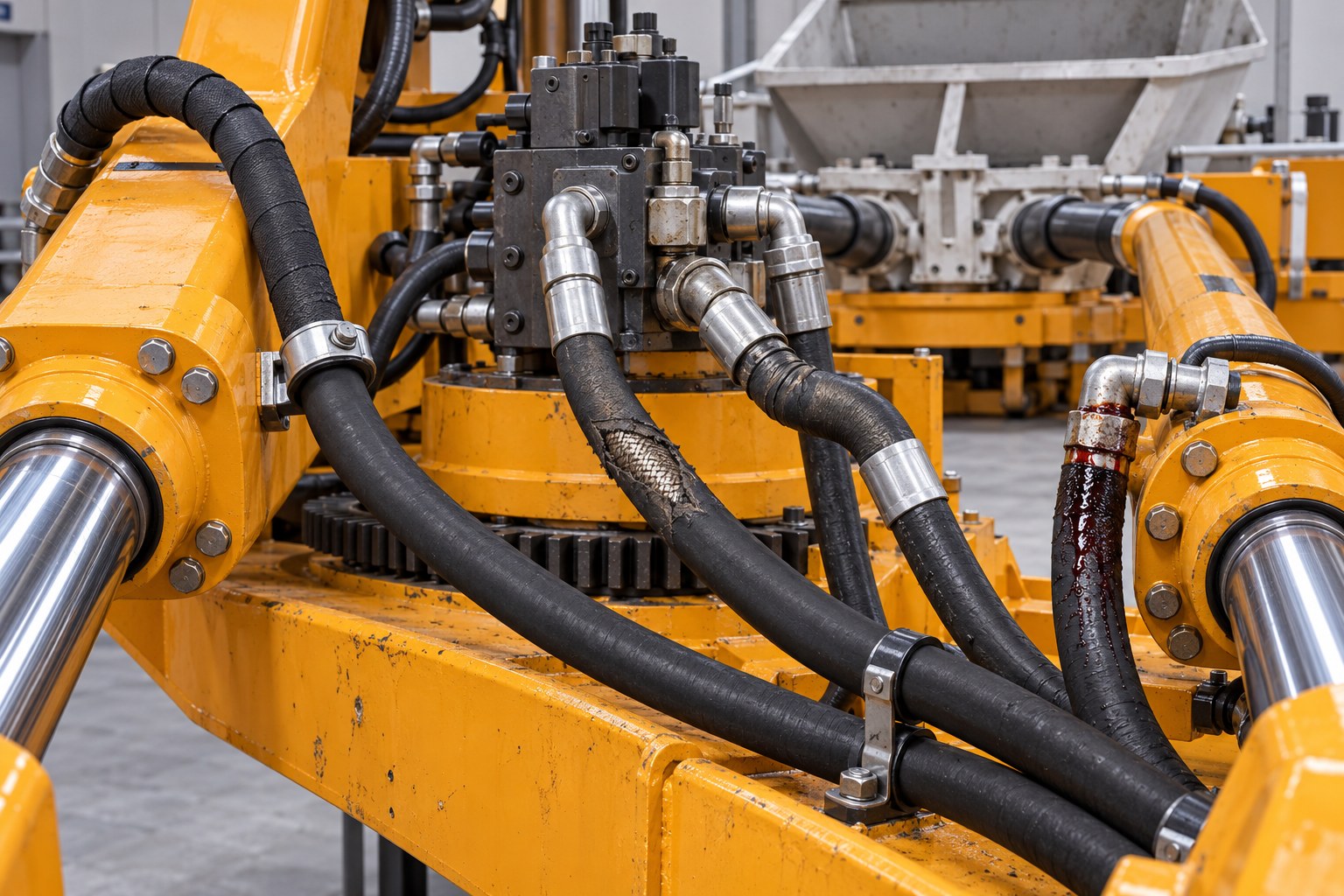
A concrete pump hydraulic hose should be replaced when its cover damage reaches the reinforcement, a fitting moves or weeps, the hose is kinked, crushed, blistered, heat-damaged, or no longer follows its intended route. Replacement is not a matter of copying length and thread size alone. The new assembly must match the circuit pressure and impulse duty, fluid and temperature range, hose bore, end connections, fitting orientation, bend radius, cleanliness requirement, and the pump manufacturer’s routing.
This article concerns the hydraulic hoses that transmit oil between pumps, valves, accumulators, filters, and actuators. It does not concern the large concrete-delivery hose carrying abrasive concrete. Confusing those two products is common in search results and supplier listings, but their construction, hazards, inspection criteria, and ordering data are different.
Why Do Hydraulic Hoses Fail on Concrete Pumps?
Concrete-pump hydraulic hoses operate in a combination of pressure cycles, vibration, contamination exposure, washdown, heat, and movement. In the valve-actuation area, each pumping cycle may reverse or change flow through the actuator circuit. Boom circuits add articulation, while hoses near the hopper can be exposed to concrete residue and aggressive cleaning. A hose may therefore fail from several mechanisms at once rather than from one obvious defect.
| Observation | Possible mechanism | What to verify before deciding |
|---|---|---|
| Polished or cut cover | Repeated contact with a bracket, another hose, or hardened concrete | Find the contact point through the full movement range; determine whether reinforcement is exposed |
| Wetness at the hose-to-ferrule area | Assembly damage, incorrect crimp, hose strain, or deterioration | Clean the area and identify the exact leak origin; do not assume the threaded joint is responsible |
| Wetness at a port or adapter | Damaged sealing face, O-ring, thread, adapter, or incorrect tightening | Distinguish port leakage from ferrule leakage before ordering a hose |
| Crack close to the coupling | Bend begins too near the fitting, insufficient support, vibration, or incorrect length | Compare the installed route with the OEM layout and the hose maker’s straight-length requirement |
| Flattening or a permanent kink | Route too tight, external crushing, or hose pulled during movement | Check minimum bend radius, clearance, and motion at every machine position |
| Blistered, soft, hard, or heat-cracked cover | Fluid incompatibility, excessive temperature, external heat, chemical exposure, or aging | Confirm fluid, actual temperature exposure, nearby heat sources, and hose specification |
| Repeated failure at the same location | Routing, pressure peaks, vibration, contamination, or component mismatch | Investigate the system cause; replacing the hose alone may only reset the failure clock |
The observation is not the diagnosis. For example, oil near a coupling can migrate from a valve block above it, and a hose that appears “too short” may actually be twisted or attached with the wrong elbow orientation. Clean, observe, and map the leak before dismantling anything. A pinhole leak must never be located with a hand: high-pressure fluid can penetrate skin. Follow the pump manufacturer’s isolation, depressurization, accumulator-discharge, and lockout procedure, and use qualified hydraulic personnel.
Which Visible Hose Defects Require Replacement?
Exposed reinforcement, a slipped fitting, a blister, a crushed section, a permanent kink, and active leakage from the hose or crimped coupling are replacement conditions, not cosmetic issues. Do not patch a pressure hose with clamps, tape, an external sleeve, or a field-applied coating. A protective sleeve can reduce future abrasion or contain spray, but it does not restore damaged reinforcement or validate the assembly’s pressure capability.
Concrete-pump OEM guidance is deliberately conservative. The official Putzmeister P 715 operating instructions assign hose-line work to people with hydraulic competence and warn that old assemblies can leak or burst. A REED-hosted truck-mounted concrete-pump manual requires damaged or weeping hydraulic hoses to be replaced rather than repaired.
Both cited manuals also state a six-year maximum that includes up to two years of storage. That is useful evidence for those specific machines, but it should not be converted into a universal rule for every concrete pump. The governing replacement interval is the applicable OEM manual, local regulation, inspection program, operating environment, and hose-system supplier guidance. Severe heat, abrasion, chemical exposure, or high impulse duty can justify earlier removal even when the calendar limit has not been reached.
Why Can a New Hose Fail Near the Ferrule?
A new hose that leaks close to the ferrule does not automatically prove that the rubber hose is defective. The bend may start too close to the coupling, the assembly may be twisted during tightening, an angled fitting may have the wrong clocking, or the hose, stem, ferrule, and crimp specification may not form a validated system. Tension from an assembly that is slightly too short can concentrate movement at the coupling. Excess length can create rubbing, looping, or interference elsewhere.
The correct response is to inspect the full assembly and its route. Verify that the hose leaves the coupling straight for the distance required by its manufacturer, stays above its specified minimum bend radius, and moves without pulling or twisting. Where the route changes plane, an elbow or adapter may be more appropriate than forcing the hose through a compound bend. Clamp location also matters: a clamp should control movement without crushing the hose or forcing a bend at the fitting.
What Must Match When Ordering a Replacement?
“Same length and same thread” is not a complete hydraulic-hose specification. The ISO 18752:2025 specification classifies wire- and textile-reinforced hydraulic hoses by pressure and performance, but it does not specify connection ends. It also states that assembly working pressure is governed by the lowest-rated component. A hose with an adequate rating cannot compensate for an unsuitable fitting, adapter, or assembly method.
A useful RFQ or workshop job card should capture the following:
- Pump manufacturer, model, serial number, and OEM hose or circuit reference where available.
- Circuit function: pump outlet, valve block, accumulator, pilot, return, case drain, cooler, boom actuator, or valve slewing actuator.
- Maximum working pressure and expected impulse duty from approved machine data—not an average dashboard-gauge reading.
- Hydraulic fluid type and relevant minimum and maximum service temperatures.
- Hose inside diameter or dash size, required flow, and allowable pressure loss.
- End-connection standard, nominal size, thread, sealing form, and male/female arrangement.
- Overall assembly length using the hose manufacturer’s defined measurement points.
- Angle and rotational orientation of elbow fittings, preferably recorded with a clocking sketch or fixture.
- Minimum bend radius, required straight section after each fitting, and actual routing envelope.
- External risks such as abrasion, hot surfaces, concrete accumulation, wash chemicals, UV exposure, or motion.
- Protective sleeve, guard, fire-resistance, electrical-conductivity, or other application-specific requirements.
- Cleanliness, flushing, capping, identification, inspection, and documentation requirements.
The Gates Safe Hydraulics guide summarizes selection with the industry mnemonic STAMPED: size, temperature, application, material, pressure, ends, and delivery. For concrete-pump service, “application” must include motion, impulse, abrasion, and routing—not merely the machine name.
How Does the Slewing-Cylinder Circuit Change the Decision?
Hoses serving the valve actuator are part of the switching system. Depending on pump design, one or two hydraulic cylinders move the S-valve or rock valve between delivery cylinders. A restricted, leaking, incorrectly routed, or internally damaged hose can alter actuator response, but slow or uneven switching can also originate in the control valve, sensor logic, accumulator, cylinder seals, mechanical binding, or valve geometry.
Before ordering a hose and a cylinder together, separate the evidence. Inspect both actuator hoses under comparable conditions, confirm that the mechanical linkage moves freely, and test according to the OEM diagnostic procedure. If the actuator itself is implicated, the mounting, ports, stroke, rod, and interface data for the Concrete Pump Slewing Cylinder must be confirmed independently. A new hose cannot correct cylinder bypass or mechanical side load; a new cylinder cannot correct a hose that collapses, leaks, or is connected to the wrong port.
Should Every Hose Be Replaced After One Failure?
Not automatically. One abrasion failure caused by a displaced clamp may be localized. A heat-aged hose in a group of same-age assemblies, repeated cover cracking across several circuits, or multiple hoses installed during the same overhaul can justify a wider replacement plan. The decision should consider common age, common exposure, circuit criticality, inspection findings, access cost, and the consequence of failure.
Record the failed hose’s location and date code before disposal. Photograph the route, supports, guards, fitting orientation, and damage. If the hose failed internally or released particles, investigate downstream contamination rather than treating the event as an external leak only. The appropriate response may include filter inspection, reservoir checks, and a controlled cleanup plan; see hydraulic-system flushing after component failure for the difference between an oil change, offline filtration, and circuit-specific flushing.
How Should a Replacement Be Installed and Verified?
Hydraulic work must begin with the machine secured against unintended movement and every relevant energy source addressed, including accumulators and gravity-loaded components. Use the pump manufacturer’s procedure. Mark connections before removal, capture oil, and cap open ports and hoses immediately. This prevents a routing error and reduces the chance that dirt enters the circuit while the replacement is being made.
Do not use the hose as a lever while tightening a fitting. Hold the assembly in its neutral orientation, apply the specified tightening method to the correct joint, and verify that the hose has not twisted. Check clearance and bend radius through the complete machine movement relevant to that circuit, not only in the parked position. A hose can look correct at rest yet rub, stretch, or fold when the valve switches or the boom articulates.
Commissioning should be controlled and model-specific. Inspect at low-risk operating conditions before full duty, observe the complete route, confirm that guards and clamps remain secure, and check for leakage without approaching a suspected high-pressure jet. After the circuit has stabilized, recheck fluid level and the relevant filter indication. If the replacement event introduced contamination or a filter warning appears, diagnose the cause rather than assuming that installing a finer element will solve it; the related guide to hydraulic-filter bypass warnings and replacement checks explains that distinction.
What Does “Clean Hose Assembly” Mean?
A visually clean exterior says nothing about particles left inside after cutting and crimping. New assemblies should be cleaned, protected, and capped to a requirement appropriate for the hydraulic system. ISO/TS 18409 describes methods for collecting contamination from hydraulic hoses or hose assemblies so cleanliness can be assessed. The purchasing specification should define the required condition and verification method rather than relying on “cleaned” as an undefined supplier claim.
Keep protective caps in place until installation. If an old hose suffered internal delamination, heat damage, or a destructive failure, the maintenance team should also examine the circuit for debris and determine which filters, valves, and actuators were downstream. Hose replacement and contamination control are linked decisions.
Concrete Pump Hydraulic Hose Replacement Checklist
- Confirm that the component is a hydraulic hose, not a concrete-delivery hose or washdown hose.
- Identify the exact leak or damage location before removal.
- Record machine, circuit, hose markings, date code, dimensions, ends, orientation, and route.
- Confirm pressure, impulse, temperature, fluid, bend-radius, and environmental requirements.
- Use a validated hose-and-fitting assembly made to the hose-system manufacturer’s specification.
- Specify internal cleanliness, end caps, identification, and required documentation.
- Correct the abrasion, heat, routing, support, or movement condition that damaged the old assembly.
- Install under the OEM safety procedure without twisting or straining the hose.
- Verify clearance through the applicable movement range and inspect during controlled recommissioning.
- Retain the failure record so repeated problems can be traced to a system cause.
Conclusion
Reliable concrete pump hydraulic hose replacement begins with diagnosis, not duplication. The damage pattern must be connected to routing, motion, pressure duty, temperature, fluid, fittings, and cleanliness. Copying an old assembly without correcting the reason it failed can reproduce the same stress in a new hose.
For a technically complete quotation, provide the machine and circuit identity, hose markings, connection details, assembly length, elbow orientation, operating requirements, photographs, and routing constraints. Final selection, installation, and replacement intervals must follow the applicable pump OEM and qualified hose-system supplier.
Technical References
- ISO 4413:2010 — Hydraulic fluid power: general rules and safety requirements
- ISO 18752:2025 — Hydraulic hose and hose assembly specification
- Putzmeister P 715 operating instructions
- REED-hosted truck-mounted concrete pump technical manual
- Gates Safe Hydraulics Pocket Guide
- ISO/TS 18409 — Cleanliness of hydraulic hose and hose assemblies