Concrete Pump Parts Knowledge
Concrete Pump S-Valve Hardfacing: Repairability, Weld Risks, and Inspection
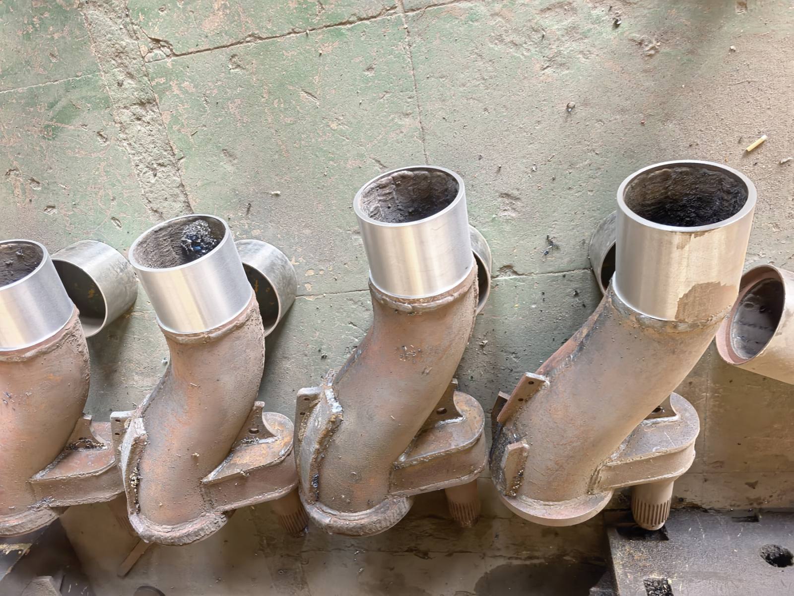
Concrete pump S-valve hardfacing can be a valid rebuild method, but only when the remaining valve body is structurally sound and the repair facility can restore the specified geometry as well as the wear layer. Hardfacing is not a substitute for adequate wall thickness, crack-free load paths, correct shaft alignment, or a qualified welding procedure. If those conditions cannot be demonstrated, replacing the S-valve is the more defensible decision.
This distinction matters because “hardfaced” can describe three different things in the concrete-pump market: a wear-resistant overlay applied during manufacture, a controlled workshop rebuild of a worn passage, or an improvised weld deposit used to fill damage. The first two may be engineered processes. The third can conceal thin metal, introduce distortion, or leave an internal profile that increases turbulence and local wear.
What Does Hardfacing Restore?
The American Welding Society defines hardfacing as a surfacing operation used to improve wear resistance. In practical repair work, it should be separated from build-up, which restores lost dimensions before the final wear-resistant layer is applied. A heavily worn S-tube may need both operations, but the materials and purposes are not interchangeable.
For an S-valve, the repair objective may include restoring an abrasion-resistant internal passage, an inlet-mouth profile, or another manufacturer-defined wear zone. Putzmeister states that the inner wall of its S-valve can be rebuilt by hard-face welding. That statement establishes that hardfacing is a recognized technique for a suitable design; it does not authorize every worn tube, every filler metal, or every field-welding method. The exact valve construction and OEM repair position still control.
A weld overlay does not automatically restore the pressure-carrying section beneath it. It also does not correct a bent shaft, worn bearing seat, displaced outlet centerline, cracked shaft-to-tube connection, or distorted sealing face. Those defects belong to a broader fitness-for-repair decision.
Factory Overlay, Repair Overlay, and Structural Welding Are Different Jobs
A factory-applied wear layer begins with known base material, controlled dimensions, a defined welding sequence, and machining allowance. A repair overlay begins with a used component whose remaining section, previous repairs, contamination history, and distortion may be uncertain. The repair shop must recreate the missing baseline before it can select a procedure.
Structural crack repair is a separate category. Depositing hard alloy over a crack does not remove the crack or prove that the load path has been restored. The defect must be characterized, the damaged material removed as required by an approved procedure, and the structural repair completed with compatible materials before any final wear layer is considered. A workshop that discusses only surface hardness has not yet defined the complete job.
Which S-Valves Are Plausible Rebuild Candidates?
The first screening question is not “How hard can the overlay be?” It is “What sound component remains after damaged material is removed?” The table below separates typical observations from the next engineering question. It is a decision aid, not a universal acceptance standard.
| Inspection observation | Repair implication | What must be verified |
|---|---|---|
| Localized wear in an existing internal overlay, with sound substrate indicated | Potential hardfacing candidate | Overlay identity, remaining base section, bond condition, repair depth, and finish geometry |
| General bore wear but stable inlet, outlet, shaft, and mounting geometry | May justify build-up plus final hardfacing | Machining allowance, heat control, minimum wall requirement, and a dimensional reference |
| Unknown previous weld layers, porosity, deep irregular cracking, or loose overlay | Old material may need removal before any new deposit | Whether removal leaves enough sound parent metal for an approved repair |
| Local wall thickness at or below the model-specific removal limit | Hardfacing alone is not evidence of restored pressure capability | OEM or responsible engineering disposition; replacement may be required |
| Crack at a shaft attachment, outlet transition, or another highly loaded region | Structural defect, not routine wear-layer renewal | Crack extent, base material, repair approval, procedure qualification, and final examination |
| Bent shaft, worn bearing seat, shifted centerline, or distorted sealing interface | Overlay cannot correct the root geometry by itself | Datum inspection, alignment, repairability of machined interfaces, and total economic scope |
Before deciding, map the remaining tube wall rather than relying on one convenient measurement. The existing LeeIndust guide to S-valve wall-thickness inspection explains why the lowest reliable local reading, tube construction, stress regions, and model-specific pressure limit matter. Hardfacing or a previous overlay can complicate ultrasonic interpretation, so an apparently stable reading must still be validated for the actual layer structure.
Why Hardness Alone Cannot Approve an S-Valve Repair
A hardness value describes one property at a stated location and test condition. It does not establish overlay chemistry, carbide distribution, impact tolerance, bond quality, dilution, deposited thickness, porosity, crack behavior, or the condition of the heat-affected zone.
AWS hardfacing guidance emphasizes that wear performance depends on the base metal, wear mechanism, process, and application details—not simply the nominal hardness of the consumable. The same source notes that excessive dilution with parent metal can reduce the carbide fraction and wear resistance of an overlay. For a curved concrete passage, uncontrolled heat input can also change geometry that later has to align with the wear plate, cutting ring, outlet, shaft, and bearings.
Concrete does not create a single wear mode. Aggregate sliding along the passage produces abrasion; larger particles and flow changes add impact; the inlet and outlet transitions can see concentrated erosion; and the valve body is repeatedly accelerated and stopped during switching. An extremely hard but brittle deposit may resist one mechanism while cracking or spalling under another. The repair specification therefore has to match the actual valve design and wear zone.
What a Controlled Hardfacing Rebuild Should Include
1. Establish identity and reference geometry
Record the pump manufacturer, exact model, serial number, S-valve part number, pressure configuration, and any design revision. Preserve a drawing, accepted sample, or measured datum set for the inlet mouth, outlet, shaft, bearing locations, sealing face, and centerlines. Copying the worn bore as the target merely reproduces wear.
2. Clean, strip, and inspect before depositing metal
Concrete residue, oil, grease, scale, loose overlay, and damaged prior welds can interfere with inspection and welding. The shop should determine where the existing overlay is sound and where it must be removed. TWI notes that hardfacing materials tend to be hard and brittle and that both the layer integrity and heat-affected-zone toughness must be controlled while preserving substrate properties.
Pre-repair inspection should document wall thickness, visible defects, crack indications where relevant, shaft alignment, bearing-seat condition, sealing-face flatness or profile, and outlet geometry. The examination method and acceptance criteria must suit the material, defect type, OEM instructions, and repair procedure. A clean-looking surface is not proof of a sound substrate.
3. Define build-up and wear-layer functions separately
If substantial material is missing, the first deposited layer may need to restore section or provide a compatible transition. The final layer supplies the required wear behavior. Choosing one hard alloy for every layer can create excessive thickness, residual stress, dilution, or an unsuitable interface. The base metal and prior overlay must be identified well enough to select compatible consumables and thermal controls.
No universal preheat temperature, interpass temperature, electrode, wire, polarity, or layer count is appropriate for all concrete pump S-valves. Those values depend on the parent material, component thickness, filler system, process, restraint, and approved procedure. Marketplace claims such as “HRC 63,” “4 mm overlay,” or a stated pumped-volume life are useful search terms, but they are not repair instructions or proof of compatibility.
4. Control heat input, sequence, and dilution
Welding heats and cools the tube unevenly. Without a controlled sequence and suitable restraint, shrinkage can move the inlet, outlet, shaft, or sealing features away from their required relationship. Excessive dilution changes the chemistry of the deposited layer; insufficient metallurgical bonding is also unacceptable. The procedure must balance bond integrity, overlay properties, heat-affected-zone condition, and dimensional stability.
Fine transverse “check cracking” can be an expected stress-relief pattern in some chromium-carbide overlays. It should not be casually accepted in every material or location. AWS distinguishes that pattern from irregular longitudinal or underbead cracking associated with possible spalling. Cracks entering the parent metal, crossing a structural attachment, or appearing outside the qualified pattern require evaluation rather than paint or another covering pass.
5. Finish to geometry, not merely to appearance
A rough deposit can narrow the passage, leave ledges that collect concrete, alter the transition at the inlet or outlet, or create high spots near mating components. After deposition, the repair may require controlled grinding or machining back to the approved internal profile and interface dimensions. Uniform shine is not a dimensional inspection.
The valve should then be checked against the recorded datums. Relevant results can include internal profile, inlet and outlet size, centerline relationship, shaft position, bearing-seat dimensions, contact-face geometry, clearances, and freedom of movement. Requirements vary by design; the old worn part is not automatically an acceptable master.
6. Examine and release the completed component
Final release should combine visual and dimensional results with the inspection required by the approved repair plan. Depending on construction and defect history, that plan may call for surface or volumetric nondestructive examination, hardness mapping, wall-thickness confirmation, or another OEM-specified test. A pressure test, if required, must follow an authorized procedure with suitable guarding; it should never be improvised from the machine’s normal operating pressure.
When Is Replacement the Better Decision?
Replacement becomes more rational when the repair cannot establish a sound substrate, sufficient remaining section, reliable alignment, or traceable process. It also becomes attractive when the combined cost of stripping, structural repair, hardfacing, machining, inspection, transport, and downtime approaches the cost and lead time of a verified replacement.
The decision should consider repeatability as well as price. A repair shop may be able to add metal, yet still lack a trustworthy drawing or datum system for returning the valve to specification. In that case, a visually impressive overlay can shorten cutting-ring life, increase switching force, or create incomplete seating. A correctly identified Concrete Pump S-Valve Assembly provides a more controlled path when the old body no longer offers a dependable foundation.
How Should the Rebuilt Valve Be Commissioned?
Before concrete is introduced, follow the pump manufacturer’s isolation, installation, lubrication, adjustment, guarding, and low-speed test procedure. Confirm that the S-valve completes travel in both directions without interference and seats against the intended wear system. A hardfaced bore does not correct a hydraulic or electrical command fault; the separate diagnostic guide for an S-valve that will not switch helps keep those causes distinct.
During initial service, monitor changeover sound, movement, sealing behavior, concrete return into the hopper, outlet leakage, abnormal heating, and early contact marks. Stop if new wear is strongly one-sided or a repaired area begins to detach. “Bedding in” should not be used to explain binding, repeated impact, or rapid loss of material.
Information for Buyer Confirmation
| Information to provide | Why it affects rebuild or replacement scope |
|---|---|
| Pump brand, exact model, serial number, year, and pump-kit revision | Separates similar-looking S-valves with different geometry or pressure configurations |
| Old part number, markings, and photos from all sides | Supports traceable identification and reveals previous modification |
| Wall-thickness map and defect locations | Shows whether sound substrate remains and where local wear controls the decision |
| History of overlays, crack repairs, and heat treatment if known | Reduces the risk of incompatible layers or hidden prior damage |
| Inlet, outlet, shaft, spline or key, bearing, and centerline dimensions | Defines interfaces that hardfacing must not distort |
| Wear plate, cutting ring, outlet seals, and bearing condition | Prevents a rebuilt valve from being installed against defective mating parts |
| Required documents and acceptance checks | Clarifies whether the quote includes procedure control, inspection, dimensional report, and final release records |
Practical Questions
Can hardfacing make a thin S-valve wall safe again?
Not by assumption. A wear overlay may restore an abrasion-resistant surface, but it does not automatically reinstate the original pressure boundary or fatigue capacity. The remaining parent metal, defect history, load path, OEM limit, and approved repair disposition must support continued service.
Does a higher HRC value always mean a longer-lasting rebuild?
No. Hardness is only one variable. Deposit microstructure, carbide distribution, matrix toughness, dilution, thickness, bond quality, impact loading, cracking behavior, and geometry all influence performance. A value without a stated layer, location, test method, and material system is incomplete.
Can a workshop hardface the S-valve without removing it?
A defensible rebuild normally requires access for cleaning, inspection, deposition control, finishing, and dimensional verification. Field access rarely provides all of those controls. Follow the OEM-approved repair route and do not weld on an installed component merely because the worn zone is visible.
Conclusion
Concrete pump S-valve hardfacing is viable when it renews a defined wear surface on a component that remains structurally and dimensionally repairable. The decision must begin with identification, wall and crack assessment, geometry, and prior-repair history—not with an advertised hardness number. A controlled rebuild separates structural repair, dimensional build-up, and final wear overlay, then verifies the finished valve against traceable acceptance criteria. When those inputs are missing, replacement is not a conservative guess; it is the more controllable engineering choice.
Technical References
- Putzmeister S-Valve Technology, NBM&CW — industry publication describing Putzmeister S-valve design and inner-wall rebuilding by hard-face welding.
- American Welding Society, 25 Hardfacing Tips: A Best Weld Overlay Practice — base-metal identification, wear mechanisms, dilution, heat control, and crack-pattern guidance.
- TWI, Weld Hardfacing — substrate metallurgy, layer integrity, heat-affected-zone toughness, and dilution considerations.
- Putzmeister P 715 operating instructions — model-specific S-transfer-tube wall-thickness inspection and safety context.