Concrete Pump Parts Knowledge
Concrete Pump S-Valve Not Switching? Diagnose Mechanical, Hydraulic, and Electrical Faults
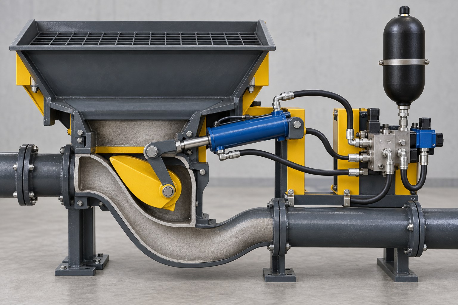
When a concrete pump S-valve is not switching, the valve body is not automatically the failed part. The fault may be upstream in the electrical command, inside the hydraulic energy path, at the shift cylinder, or in the mechanical load between the cylinder and transfer tube. The fastest reliable diagnosis is to identify where the sequence stops: command, oil flow, actuator travel, valve rotation, or final seating.
This distinction matters on a jobsite because several faults produce the same surface symptom. Hardened concrete can physically obstruct the transfer tube. A solenoid can receive no command. A directional cartridge can stick. An accumulator circuit can lose usable energy. A shift-cylinder seal can bypass internally. A linkage can move without bringing the valve fully onto the opposite cylinder port. Increasing pressure or adjusting the valve before locating the failed stage can damage wear parts and conceal the original evidence.
What Does “Not Switching” Actually Mean?
Concrete pump terminology varies. The moving material valve may be called an S-valve, S-tube, transfer tube, swing tube, or shuttle tube. Its hydraulic actuator may be described as a shift cylinder, swing cylinder, slewing cylinder, or transfer-tube plunger cylinder. Before troubleshooting, name the observation rather than relying on the general complaint “the S-valve is stuck.”
| Observed behavior | Fault stage to investigate first | What the symptom does not prove |
|---|---|---|
| No shift command or solenoid indication at the expected changeover | End-position sensor, wiring, supply voltage, controller output, interlock, relay, or solenoid circuit | It does not prove that the hydraulic valve or S-tube is mechanically seized. |
| Command is present, but the shift cylinder does not move | Directional valve, circuit pressure and flow, accumulator where fitted, hose path, or actuator | It does not prove that the S-valve body needs replacement. |
| The actuator begins moving but is slow, hesitant, or stalls | Hydraulic energy loss, internal bypass, restricted flow, mechanical drag, buildup, or excessive adjustment load | Slow movement alone cannot distinguish low pressure from high resistance. |
| The lever and valve move, but the inlet does not fully cover the next cylinder opening | Cylinder stroke or adjustment, lever position, spline or pin wear, shaft support, end position, or interference | Motion at the rod is not proof of correct valve alignment. |
| The fault occurs in one direction only | Direction-specific coil, wiring, cartridge, hose, cylinder chamber, linkage geometry, or obstruction | A shared supply problem is possible, but asymmetry provides a stronger localization clue. |
This classification prevents three different failures from being treated as one. A pumping ram that reverses early is a short-stroke problem; a transfer valve that receives no switching command is a control problem; and a transfer valve that rotates but does not seat is an end-position or mechanical problem. They can disturb the same changeover event, but they require different tests.
Make the Hopper and Stored-Energy System Safe First
Do not inspect an S-valve by reaching through the hopper grille or by loosening a hydraulic connection to see whether oil appears. The Putzmeister safety manual identifies crushing and shearing hazards from the transfer tube and agitator in the hopper area. Hydraulic accumulators and trapped material can retain energy after the prime mover stops.
Follow the shutdown, pressure-release, lockout, hopper-access, and blocking procedure for the exact pump. Guards, interlocks, emergency stops, and mechanical restraints must not be treated as diagnostic inconveniences. A manual override or cylinder-jog function is useful only when the OEM procedure permits it and personnel remain outside the danger zone.
Follow the Shift Sequence From Signal to Seating
A symptom-led workflow is more efficient than changing the most visible part. Trace the sequence in the order the machine uses it:
- End of pumping stroke is detected. A proximity switch, pressure event, position sensor, or other model-specific logic tells the control system that changeover should begin.
- The controller issues a direction command. The output energizes the appropriate relay, coil, or electrohydraulic control.
- The directional valve routes hydraulic oil. The shift circuit must have adequate pressure, usable flow, and a return path. Some pumps use an accumulator to supply a short burst of energy.
- The actuator develops force and travel. The shift cylinder must move without excessive internal leakage, external leakage, bent hardware, or mounting movement.
- The linkage rotates the material valve. Pins, bushings, clevises, lever hubs, splines, shafts, and bearings must transmit motion without lost travel or binding.
- The S-valve reaches and holds its end position. The valve inlet, wear ring, and wear plate must align as designed without debris or excessive preload preventing full seating.
The REED trailer-pump troubleshooting guide reflects this system view. For improper S-tube shifting it lists mechanical buildup, excessive adjustment, binding, insufficient lubrication, accumulator and shift-pressure faults, manifold or solenoid problems, internal shift-cylinder leakage, and incomplete linkage positioning. These are model-family examples, not universal settings or repair instructions, but they show why one symptom must be divided into several fault branches.
Mechanical Causes: Can the Valve Move Freely and Reach the Port?
A hydraulic actuator cannot correct a physically obstructed or over-loaded valve. After the machine has been made safe and cleaned according to the OEM procedure, inspect the material path and the mechanical load path.
Concrete Buildup and Trapped Aggregate
Hardened material around the wear ring, wear plate, thrust element, valve inlet, or hopper can stop rotation or prevent the last part of travel. A fresh blockage may also leave aggregate where the moving contact faces cannot pass. The location matters: concrete behind a compensation component can change its available movement, while debris at a cylinder opening can prevent the valve from covering the port even though the lever travels.
Do not use higher hydraulic pressure to crush an unidentified obstruction. That can transfer load into the shaft, lever, cylinder mounts, wear plate, or hopper structure. Clean and inspect under the model procedure, then check whether the valve moves freely through the approved service test.
Adjustment, Lubrication, and Wear Contact
An over-tightened adjustment can create more sliding resistance than the shift circuit was designed to overcome. Conversely, an exhausted compensation element or badly worn contact pair can allow leakage even when the valve reaches its stop. The separate guide to S-valve wear-ring adjustment explains why adjustment cannot restore a tilted shaft, grooved plate, damaged ring, or seized thrust mechanism.
Lubrication faults can add resistance at the valve shaft, outlet bearing, linkage pins, or cylinder joints. A full grease reservoir does not prove that lubricant reaches every point. Verify the path and actual discharge using the method specified for the pump; the LeeIndust article on S-valve lubrication and grease-path diagnosis covers that distinction.
Lost Motion in the Linkage
Watch the complete load path from actuator mount to valve shaft during an approved low-risk test. A loose clevis pin, oval bushing, cracked lever, slipping spline, worn hub, or moving cylinder mount can consume actuator travel. The rod may complete its stroke while the S-valve stops short of the cylinder opening.
Marking relative positions before dismantling can help identify movement, but it is not a substitute for dimensional inspection. If the complaint began immediately after a hopper rebuild, confirm lever orientation, spline indexing, cylinder-rod adjustment, bearing assembly, and all retained spacers against the correct parts and service information.
Hydraulic Causes: Is Enough Energy Reaching the Actuator?
A command at the solenoid does not prove that useful hydraulic power reaches the cylinder. The circuit must charge, hold, direct, and discharge oil at the required rate while the actuator and return path remain serviceable.
Official Multiquip LS450 troubleshooting information separates a shuttle cylinder that does not stroke from one that strokes slowly. Its model-specific fault list includes accumulator-system pressure, relief-valve contamination, a non-energized swing solenoid, directional-valve function, flow-control condition, engine speed, system pressure, and inadequate lubrication at a loaded seal. The published pressure values belong to that model and must not be copied to another pump.
Accumulator and Charge-Circuit Behavior
Where an accumulator supports valve changeover, separate nitrogen precharge from hydraulic charging pressure and from the live pressure seen during a shift. Low usable stored energy can produce a weak or incomplete changeover, but an accumulator reading can also be affected by the charge pump, unloader, check valve, relief valve, manifold leakage, actuator bypass, and gauge condition.
The article on concrete pump accumulator pressure explains these pressure terms and why a value from another model is unsafe. Record charge time, cut-off behavior, pressure decay with the machine in the specified test state, and pressure during the fault. Do not assume that adding nitrogen repairs a hydraulic leak.
Directional Valves, Relief Cartridges, and Contamination
A coil may energize while its spool or cartridge fails to move fully. Contamination, coil failure, low voltage under load, damaged connectors, a sticking manual override, or internal valve wear can interrupt flow. Schwing’s technical service-bulletin index, for example, documents a model-specific SP Rock Valve “gunning” issue associated with a hydraulic check cartridge stuck open by oil contamination. That bulletin does not establish a universal diagnosis, but it confirms that clean electrical commands can coexist with a contaminated hydraulic control element.
If a cartridge is found contaminated, identify the contamination source and cleanup scope before installing another part. The recent LeeIndust guide to hydraulic oil contamination testing explains why appearance alone cannot establish oil cleanliness or the failed component.
Shift-Cylinder Internal Bypass
Internal leakage can let pressurized oil cross a piston seal instead of producing force at the rod. The external symptom may be slow movement, stalling under concrete load, drift away from an end position, or a circuit that recharges unusually often. External leakage is not required.
Use the OEM isolation or leakage-test procedure. Do not improvise by disconnecting a pressurized hose. The result must also be separated from directional-valve leakage and mechanical resistance. If cylinder bypass is confirmed, identify the exact Concrete Pump Slewing Cylinders by pump model, part number, mounting centers, pin sizes, port details, stroke, retracted and extended lengths, and left/right arrangement where applicable.
Electrical and Control Causes: Was a Valid Command Issued?
If no shift command appears at the expected instant, start before the hydraulic actuator. Confirm that the pumping ram actually reached the model’s changeover condition and that the relevant sensor input changes state. Then follow the control path through connectors, harnesses, interlocks, controller output, relay, and coil.
Voltage must be checked under the correct operating condition, not inferred from an indicator lamp. A corroded connector or weak supply can show nominal voltage with no load and collapse when the coil is energized. Coil resistance or current should be compared with the component and OEM documentation; one internet value does not apply to every voltage, coil design, or temperature.
An approved manual-jog function can be a useful dividing test. If the valve shifts correctly during manual hydraulic control but not during automatic cycling, the evidence points toward sensing, logic, or the automatic command path. If it still fails under manual control, the investigation moves toward the hydraulic and mechanical stages. Manual operation is a diagnostic aid, not permission to bypass an interlock or continue production with a defective control system.
A Practical Fault-Isolation Workflow
- Record the exact symptom. Note direction, concrete load, oil temperature, pump speed, warning messages, recent repairs, and whether the failure is constant or intermittent.
- Make the machine safe and remove misleading residue. Use the OEM cleaning and isolation procedure. Do not diagnose through a hopper containing an unknown obstruction.
- Compare unloaded and loaded behavior only where the manual permits. A valve that moves when clean but stalls with pumpable material may have marginal hydraulic energy, excessive mechanical drag, or a load-sensitive internal leak. It still requires measurement.
- Confirm the command chain. Verify sensor input, controller output, supply under load, connector condition, and the correct directional coil.
- Confirm hydraulic behavior. Record specified charge, hold, shift, and return observations using approved test points and calibrated instruments. Use only model-specific limits.
- Evaluate the actuator separately. Check mounting, pins, rod travel, external leakage, internal bypass under the OEM test, and whether the two directions behave differently.
- Inspect the mechanical path. Check buildup, lubrication, adjustment, lever position, hub or spline fit, shaft support, wear-ring movement, and final alignment with both cylinder ports.
- Repair the verified cause, then recommission at controlled speed. Confirm repeated complete shifts, stable pressure behavior, correct seating, no abnormal impact, and no new leakage before returning to normal pumping.
A measurement is most valuable when it closes one branch. “Pressure is present” is not enough; record where, when, and under what state it was measured. “The cylinder moves” is also incomplete; record full travel, time, direction, load, and whether the valve actually seats.
Information for Buyer Confirmation
| Replacement scope | Information to provide | Why it matters |
|---|---|---|
| S-valve or S-tube | Pump manufacturer, model, serial or production range, verified part number, outlet size, shaft or spline details, wear-face dimensions, photos from several angles | Similar-looking valve bodies may differ in geometry, interfaces, and installed orientation. |
| Shift or slewing cylinder | Part number, left/right position, bore and rod size if documented, stroke, closed and open length, mounting centers, pin diameters, port type and orientation, photos | Force, travel, timing, mounting, and hose routing must match the installed system. |
| Solenoid or hydraulic cartridge | Valve-manifold identification, cartridge code, coil voltage, connector style, cavity or OEM reference, fault direction, wiring diagram reference | Physical fit does not confirm electrical or hydraulic function. |
| Lever, pin, or bushing | Center distances, pin and hole dimensions, hub or spline form, offset, orientation, wear measurements, mating-part condition | Small losses in several joints can add up to incomplete valve travel. |
| Wear ring, plate, thrust, or seal parts | Valve type, part references, contact pattern, remaining adjustment or compensation travel, mating-surface condition, photos after cleaning | Replacing one wear part cannot correct a damaged mating face or misaligned valve axis. |
Before ordering a complete Concrete Pump S-Valve Assembly, document which stage failed. If the existing valve rotates freely and reaches both ports during the approved mechanical check, the stronger evidence may point toward the actuator, control circuit, or linkage rather than the valve body. If the valve is cracked, severely worn, incorrectly aligned, or cannot seat because its own interfaces are damaged, a valve replacement may be justified—but related bearings, wear parts, lever geometry, and shift-cylinder condition still need confirmation.
Conclusion
A concrete pump S-valve that does not switch is a sequence fault, not a single-component diagnosis. First establish whether the machine generated a valid command. Then verify whether hydraulic energy reached the actuator, whether the actuator completed its travel, whether the linkage transmitted that travel, and whether the valve reached the correct seating position without obstruction or excessive drag.
This approach turns a vague complaint into testable branches. It also prevents common but costly responses—raising pressure, loosening an adjuster, replacing an accumulator, or ordering a complete valve—before the evidence shows which stage has actually failed.